
How to Use a Plan Region in Revit for Local View Ranges


A Plan Region in Revit is a closed sketch boundary that overrides the view range for one part of a plan view, letting that section show a different cut plane, top, or bottom than the rest of the drawing. It solves the split-level floor, the clerestory window sitting above the standard cut plane, and the mezzanine that never shows up right no matter how you tweak the main view range.
Here’s the fast version, then we’ll get into the details that trip people up.
Open the plan view where the element is missing or cut wrong.
Go to the View tab, then Create panel, then the Plan Views dropdown and select Plan Region.
Sketch a closed loop around the problem area using Rectangle, Line, or Pick Lines.
Open View Range on the Properties palette and adjust the Top, Cut Plane, Bottom, and View Depth for that local area.
Click Finish Edit Mode.
Check the region: the window, stair, or split floor should now display correctly without affecting anything outside the boundary.
That’s the whole trick. A plan region defines a cut plane at a different height than the one used for the rest of the plan, and it’s built specifically for split-level plans or elements sitting above or below the standard cut line. Once you see it work once, you’ll wonder why you spent so long fighting the global view range instead.
Key Takeaways
Plan Regions give Revit users a way to override the view range inside one small area of a plan without touching the rest of the drawing, and mastering their view-range fields and limitations prevents most coordination headaches.
Point | Details |
Core function | A plan region overrides Top, Cut Plane, Bottom, and View Depth inside a closed sketch boundary only. |
Best use cases | Reach for one with clerestory windows, split-level floors, mezzanines, and stair openings above the standard cut plane. |
Copy behavior | View range settings transfer intact when a plan region is copied within a view or pasted into another plan view. |
Key limitation | Plan regions cannot overlap, are view-specific by default, and are unreliable for controlling MEP visibility. |
Troubleshooting first step | Check whether the region’s annotation category is visible and whether the element truly sits inside the boundary. |
Skill development | S15studio’s Revit courses build view-range and coordination practice into real project exercises with trainer feedback. |
Table of Contents
When Do You Need a Plan Region in Revit?
Not every visibility problem calls for a plan region. Most of the time you need one when a single feature refuses to show up correctly while everything else in the plan looks fine. Here are the situations where it actually earns its keep:
A clerestory or high window sits above the standard cut plane and disappears from the plan.
A split-level floor has two finished floor elevations in one drawing.
A mezzanine or loft area needs its own cut height to read correctly.
A stair opening or guardrail needs a different view depth to show railings without hiding the floor below.
Furniture, casework, or hosted elements sit outside the normal cut range in just one room.
Picture a single-story house with a two-foot clerestory band above the standard 4-foot cut plane. Raise the whole view’s cut plane to catch that window, and every other window on the plan disappears or shows the wrong sill line. Draw a plan region around just that wall segment instead, raise the cut plane locally, and the rest of the floor plan stays untouched. That’s the entire value proposition in one example.
Before you reach for a plan region, though, consider whether an underlay or a duplicated view solves the problem more cleanly. If you need to reference an entire adjacent level rather than a single detail, an underlay is usually faster to set up and easier for other team members to understand at a glance.
How Do You Create a Plan Region in Revit?
The workflow is short, but a few steps determine whether the region behaves the way you expect.
Open the plan view that needs the local adjustment.
Navigate to the View tab, then the Create panel, then click the Plan Views dropdown and select Plan Region.
Revit switches into sketch mode. Draw a closed boundary using the Rectangle, Line, or Pick Lines tool. Any gap in the loop will stop you from finishing the edit, so trace existing walls with Pick Lines when precision matters.
With the sketch still active (or after selecting the finished region), open the Properties palette and click Edit next to View Range. This is where you set the local Top, Cut Plane, Bottom, and View Depth values, distinct from the view’s global settings.
Click Finish Edit Mode to commit the sketch and the view range values together.
Zoom into the region and confirm the intended element now displays. If it doesn’t, the cut plane probably still misses it, which we’ll fix in the troubleshooting section below.
Trainers who teach this workflow for split-level areas, mezzanines, and stair openings usually recommend sketching loosely first and tightening the boundary after you confirm the view range values work. Get the visibility right, then clean up the geometry.
Pro Tip: Rename each plan region something specific, like “Clerestory - North Wall” or “Mezzanine Cut Plane,” using the Comments field or a shared parameter. On a project with a dozen regions across multiple floors, an unnamed sketch boundary is nearly impossible to track down six months later.
Can You Edit or Copy a Plan Region After Creating It?
Yes, and the behavior here is where a lot of Revit users get surprised the first time.
You don’t need to re-enter sketch mode for small adjustments. Select the plan region on the plan, and Revit shows shape handles on the boundary lines and corners. Drag those handles to resize or reshape the region without triggering a full edit session, which is the fastest way to nudge a boundary a few inches after a design change.
Copying a plan region within the same view keeps its shape and its view range settings intact.
Pasting a plan region into a different plan view also retains its view range values, which is genuinely useful when a building has repeating floor plates with the same clerestory condition on multiple levels.
Plan regions are view-specific by default. A region drawn in one plan view has no effect on any other view, even a duplicate of the same level, unless you copy it over.
Say you have a repeating clerestory condition on floors two through five of an office building. Draw and tune the plan region once on floor two, then copy and paste it into the plan views for floors three, four, and five. The view range values transfer exactly, saving you from re-tuning offsets four separate times. Just double check the boundary geometry still lines up if the floor plans aren’t perfectly identical.
How View Range Settings Work Inside a Plan Region
The View Range dialog inside a plan region has the same four fields as the global view range, but they only apply within the sketched boundary.

Top sets the highest cut elevation. Cut Plane is the horizontal slice Revit uses to determine what gets shown with cut linework versus projection. Bottom sets the lowest visible elevation. View Depth extends visibility below the bottom plane for elements you want to see in gray, uncut linework, like a floor slab on the level below.
Revit enforces a logical hierarchy between these values. The Top must sit above the Cut Plane, and the Cut Plane must sit above the Bottom offset. Get the order wrong and Revit either rejects the input or displays the plan incorrectly, so if a region isn’t behaving, check the numbers against each other before assuming something else is broken.
Here’s a typical numeric scenario for a clerestory band sitting well above the standard cut height:
View Range Field | Typical Value (Clerestory Example) | What It Accomplishes |
Top | 7’-6" above level | Captures the full height of the high window band |
Cut Plane | 7’-6" above level | Slices through the window itself instead of the wall below |
Bottom | 0’-0" (level) | Keeps the floor plane visible at the normal reference |
View Depth | 0’-0" (matches Bottom) | No additional projection below floor level needed |
Change the Cut Plane to 7’-6" only inside that region, and the window shows with proper cut linework while the rest of the plan keeps its standard 4-foot cut height. That’s the entire mechanism, expressed as four numbers.
What Are the Limitations of Plan Regions in Revit?
Plan regions solve a narrow problem well, but they have real limits worth knowing before you rely on them for something bigger.
Plan regions cannot overlap each other in the same view. Revit will block you from finishing a sketch that crosses an existing region’s boundary.
They’re view-specific by default, so a fix in one plan view doesn’t automatically appear anywhere else unless you copy it.
They primarily control visibility for hosts and hosted elements like walls, windows, and doors. MEP elements often don’t respond predictably to a plan region’s view range, so ductwork or piping that vanishes needs a different fix.
Plan regions export and print exactly as they appear on screen, including their boundary lines if the annotation category is turned on.
Hiding the plan region’s annotation category removes the visible boundary line but leaves the view range override fully active, which can cause linked model elements to display at unexpected elevations during coordination reviews if nobody remembers the region is there.
That last point deserves a second look. On a coordinated project with linked architectural and structural models, an invisible plan region is one of the sneakier sources of “why does this element look wrong in the link” complaints. Turn on the Plan Region category temporarily in Visibility/Graphics Overrides to audit a view before blaming the linked file.
Method | Best For | Not Best For |
Plan Region | Small, local cut-plane exceptions (a window, a split floor edge) | Whole-level references or MEP-heavy visibility control |
Underlay | Showing an entire adjacent level as background reference | Precise, element-specific cut plane changes |
Duplicated/dependent view | Large plans split by matchline or heavy MEP coordination | Quick single-element fixes on an otherwise simple plan |
The best-practice guidance from Revit trainers is consistent on this: plan regions for local exceptions, underlays for whole-level context, and matchlines or dependent views when a plan is genuinely too large or too complex for one sheet.
Troubleshooting Plan Regions and Trainer Pro Tips
When a plan region doesn’t behave, work through this checklist before assuming something is broken:
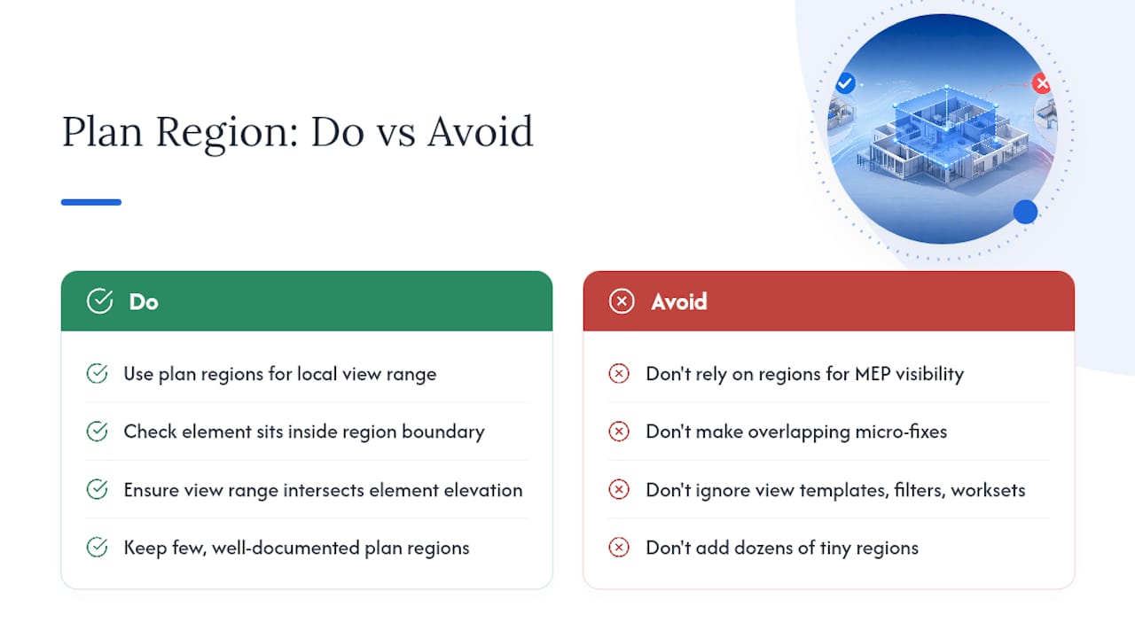
Confirm the Plan Region annotation category is visible in Visibility/Graphics Overrides so you can see and select the boundary.
Check that the element you’re trying to reveal actually sits inside the sketched boundary, not just near it.
Verify the View Range values (Top, Cut Plane, Bottom, View Depth) genuinely intersect the element’s real elevation.
Look for a view template, filter, phase setting, or workset visibility rule overriding the element separately from the view range.
If the element is MEP (duct, pipe, cable tray), test whether a duplicated view or a visibility filter gets more reliable results than a plan region.
A few habits separate clean project files from ones that generate confused questions in every coordination meeting:
Name every plan region with something specific rather than leaving it unlabeled.
Manage annotation visibility deliberately. A saved view template can hide plan region boundaries for presentation sheets while keeping the underlying view range override active.
Prefer duplicated cropped views for heavy MEP coordination rather than stacking plan regions that don’t reliably control mechanical or electrical visibility.
Standardize units and naming across your office template so every plan region follows the same convention.
Track plan regions in your office standards document, especially on repeating floor plates, so the next person on the project doesn’t rebuild what already exists.
On large, multi-discipline projects, fewer plan regions paired with duplicate views tend to cause less confusion than a plan riddled with a dozen small, overlapping-adjacent regions. Reserve plan regions for genuine local exceptions, and lean on duplicated views or matchlines once a floor plate gets complicated enough that six people need to work on it at once.
Why Plan Regions Trip Up So Many Revit Users
I’ve watched the same mistake happen in classroom after classroom: someone spends twenty minutes cranking the global view range up and down, watching one window appear while three others disappear, before ever discovering the Plan Region tool exists. It’s not a knowledge gap so much as a visibility gap. Revit buries this tool one dropdown deep, and nothing in the interface tells you it’s the answer to the problem you’re staring at.
The bigger issue I see in real project files isn’t creating plan regions. It’s forgetting they exist. A region gets added under deadline pressure, its boundary gets hidden for a cleaner presentation sheet, and six months later someone on the structural team is baffled by why a linked wall shows up wrong in a coordination view. That’s not a Revit bug. That’s an undocumented plan region nobody wrote down anywhere.
Treat every plan region like a piece of project data, not a quick fix. Name it, note why it exists, and revisit it when the design changes. Do that consistently and you get cleaner drawings, fewer late-stage sheet issues, and coordination reviews that don’t turn into archaeology.
Learn Plan Regions and View Control Hands-On With S15studio
Reading about view ranges gets you started, but nothing beats working through real project files where a clerestory window or a split-level floor forces you to actually apply the settings correctly. S15studio’s project-based courses build exactly that kind of practice into the curriculum, with direct trainer feedback so you’re not guessing whether your view range values are right.
If you’re still building foundational Revit skills, the beginner-to-intermediate course walks through view management alongside the other core workflows you’ll use daily. Already comfortable with the basics and ready to tackle complex coordination, multi-discipline projects, and advanced view control? The Revit Master Class goes deeper into exactly the kind of view-range and visibility troubleshooting covered here, with real project exercises and lifetime access to the materials. Pick the level that matches where you’re at and start working through project files instead of guessing your way through another split-level plan.
Frequently Asked Questions
What is the difference between a Plan Region and a crop region in Revit? A plan region changes the view range (cut plane, top, bottom) inside a small local area, while a crop region controls what portion of the model is visible on the sheet or in the view window. They solve different problems and can be used together in the same view.
Can I use a Plan Region to control MEP element visibility? Not reliably. Plan regions primarily affect hosts and hosted elements like walls, doors, and windows. For ductwork, piping, or cable tray, a filter or a duplicated view usually gives more predictable results.
Why isn’t my element showing up even after I created a Plan Region? Check that the element sits fully inside the sketched boundary and that the View Range values you set actually intersect its real elevation. A view template, filter, or workset setting elsewhere in the view can also override what the plan region is trying to show.
Do Plan Regions show up when I print or export a view? Yes. A plan region’s view range effect and its boundary line (if the annotation category is turned on) both appear in prints and exports exactly as shown on screen.
How many Plan Regions should one plan view have? As few as the project genuinely needs. A handful of well-documented regions is far easier to manage than a dozen overlapping micro-fixes. On large or MEP-heavy plans, a duplicated cropped view often replaces several plan regions with a cleaner result.
Sources
Autodesk’s own documentation remains the most reliable reference once you need to check an edge case the trainer-style guides don’t cover in depth.
Recommended
Comments