
Revit Building Pad Explained for Architects

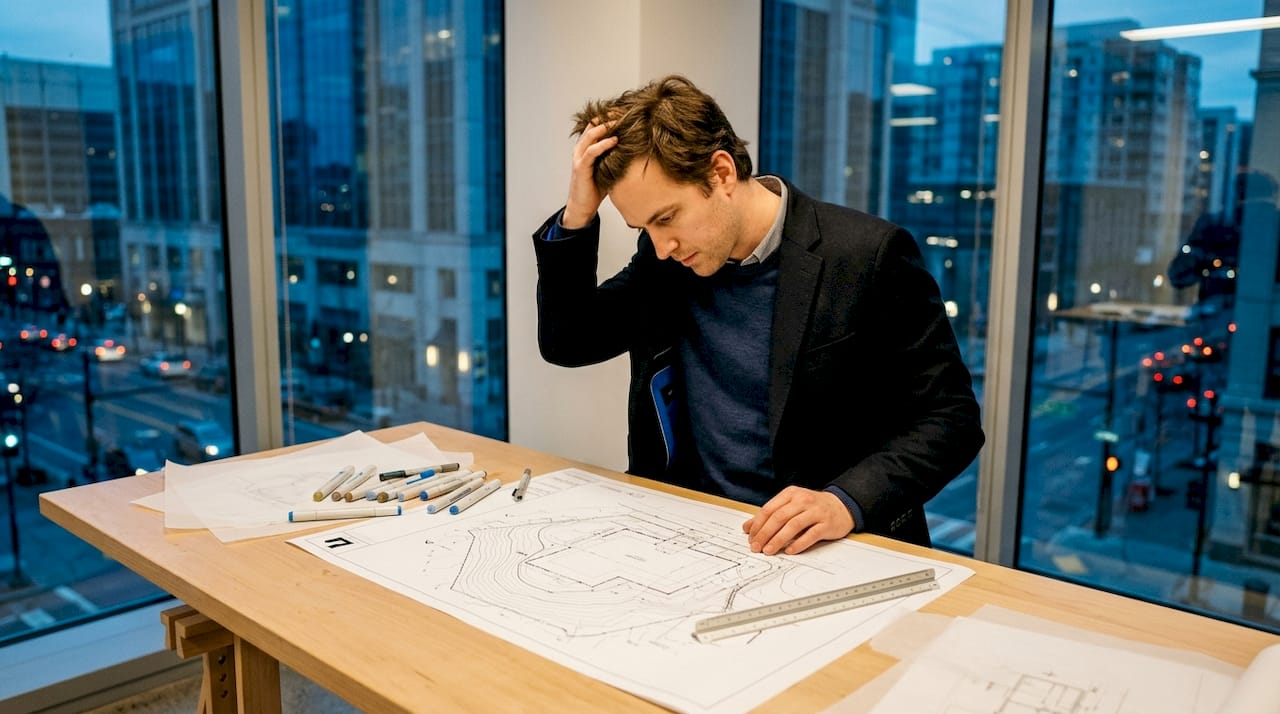
A Revit building pad is a topography modification element that cuts or fills an existing topo surface to create a controlled, flat or sloped base for a building footprint. Architects working on site-heavy projects rely on this tool to model realistic terrain transitions, generate accurate grade lines in elevation views, and feed cut/fill volume calculations. With Revit site design techniques evolving through recent software versions, understanding how building pads work, where they fall short, and how to use them without errors is a skill every design professional needs on complex projects.
How does the building pad tool modify existing topography in Revit?
A building pad physically reshapes the topo surface by cutting into or filling up the terrain within its sketched boundary. The pad sketch defines the footprint edge, and Revit adjusts the topography geometry to meet that boundary at the specified elevation. This is the core mechanism behind Revit topography and building pads working together as a site modeling system.
Building pads act as critical site modeling elements that physically modify topography. In Revit versions prior to 2024, building pads drove cut/fill volume calculations directly. That relationship changed significantly with the Toposolid tool introduced in Revit 2024.
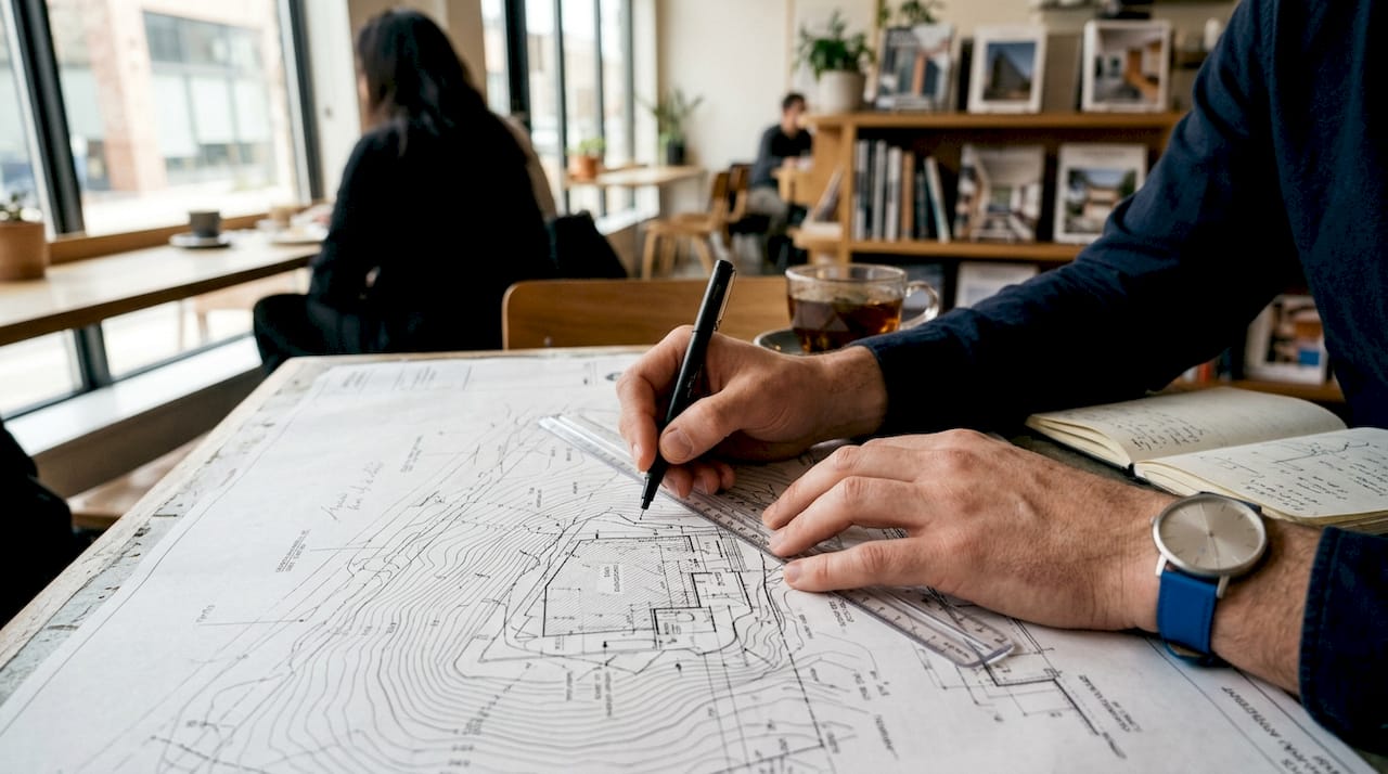
Since Revit 2024, the traditional building pad no longer handles cut/fill volume calculations. New workflows use the Toposolid and Excavation tools instead, with floor elements representing the pad surface. Architects still working in pre-2024 projects will encounter the classic pad workflow, so knowing both approaches matters.
Common issues with building pads not cutting the topo surface include:
Overlapping sketch lines within the pad boundary, which cause Revit to reject the sketch or produce unexpected geometry
Complex geometry conflicts where the pad boundary intersects another pad or site element
Incorrect elevation settings where the pad offset does not match the intended finished floor level
Topo surface gaps where the topography mesh does not extend fully beneath the pad boundary
Pro Tip: If your pad is not cutting the topo, open the pad sketch and look for duplicate lines stacked on top of each other. Delete the extras, finish the sketch, and the topo cut will resolve immediately.
What techniques optimize building pad creation in Revit site design?
Efficient pad creation starts before you draw a single sketch line. Architects who front-load their pad boundary planning with permanent reference geometry save significant rework time on complex sites.
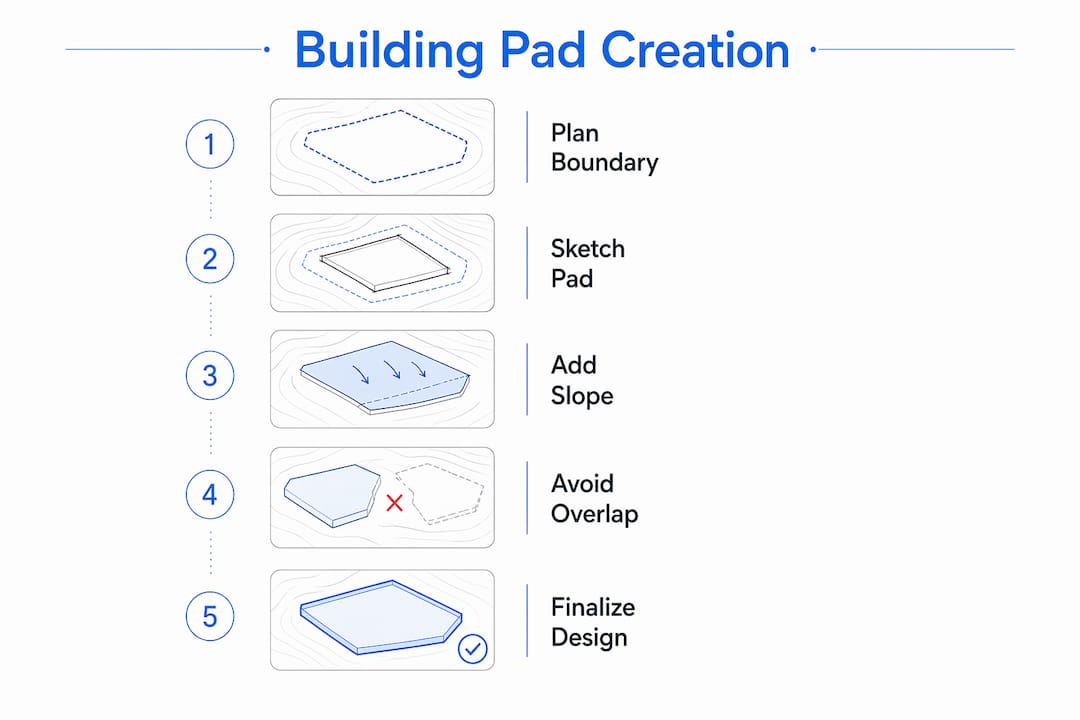
Place Reference Planes at every common boundary line before sketching pads. When you need to shift a pad edge, moving the Reference Plane updates all pads locked to it simultaneously. This approach preserves site design coherence across multiple pads without manual re-sketching.
Follow this sequence for reliable pad creation on sloped or multi-level sites:
Set up Reference Planes at all shared pad boundaries before entering sketch mode on any pad.
Sketch the first pad boundary using the Reference Planes as snap targets, locking sketch lines to the planes.
Copy the shared boundary sketch line from the first pad and paste it into the adjacent pad sketch. This guarantees perfect edge alignment without overlap.
Apply a Slope Arrow inside the sketch if the pad needs to slope. Set the height at tail and head, or define a slope percentage, to model ramps, sloped paving, or graded aprons.
Set the pad offset from the level to match your finished floor or site datum.
Finish the sketch and check the 3D view to confirm the topo cut reads correctly.
Slope Arrows in building pad sketch mode allow you to model ramps, paving, and footpaths with accurate site-specific slopes. This makes sloped pads far more useful than a flat slab for representing real site conditions.
Avoid overlapping building pads at all costs. Paste shared boundary sketches into adjacent pads to achieve perfect edge alignment. Overlapping pad boundaries are the single most common cause of topo-cutting failures in complex site models.
Pro Tip: Use the “Copy to Clipboard” and “Paste Aligned to Same Place” commands to transfer shared sketch lines between pads. This is faster and more accurate than re-drawing the shared edge.
How do building pads affect elevation views and building coordination?
Building pads generate the grade line that appears at the base of a building in elevation views. This is one of the most misunderstood functions of the tool, and skipping the pad placement is the reason many Revit elevation views show walls floating above or cutting awkwardly through terrain.
Revit will not automatically generate a grade line where the terrain meets building walls. The building pad explicitly defines this intersection. Without a pad, the elevation view lacks the visual ground line that communicates how the building sits on the site.
Building pads force topography to reveal precise building footprint lines and anchor walls along complex site contours. Architect Marcello Sgambelluri describes this as using pads as sacrificial site geometry elements. The pad exists not just to cut terrain but to control the visual and geometric relationship between the building and the ground.
Key coordination points between building pads and building elements:
Wall base alignment: The pad top surface should match the finished floor level so exterior walls read correctly in section and elevation.
Footprint matching: The pad boundary should align with the exterior face of the building’s outer walls, not the structural grid or interior face.
Room bounding: Sloped building pads are room-bounding elements, which means they affect room area and volume calculations when the site slopes through a habitable space.
Elevation graphics: A correctly placed pad produces a clean, dark grade line in elevation that matches construction document standards.
What are the real-world site preparation implications of building pads?
The digital building pad in Revit mirrors a physical process on site. Understanding that process helps architects model pads with realistic dimensions and slopes, and it improves coordination with civil and structural engineers.
Real-world site pad preparation involves clearing vegetation, stripping topsoil, rough grading, and compacting fill in lifts to 90–95% relative compaction per ASTM D1557 standards. Costs for this work range from $3,500 to $12,000 depending on site conditions. That cost range reflects why accurate digital modeling of cut and fill volumes matters to project budgets.
Drainage slopes of 2% or greater away from the building pad are required to direct water away from the foundation. Modeling this slope in Revit using a sloped pad or graded topo surface gives the civil engineer a usable reference for drainage design. Ignoring drainage slope in the model leads to coordination errors that show up late in the design process.
The table below summarizes the key site preparation parameters architects should reflect in their Revit pad modeling:
Site Parameter | Standard or Requirement | Modeling Implication |
Compaction | 90–95% per ASTM D1557 | Set pad depth to reflect stripped topsoil and fill layers |
Drainage slope | 2% minimum away from building | Use Slope Arrow in pad sketch or grade topo surface accordingly |
Topsoil stripping | 6–12 inches typical | Offset pad elevation below finished grade to account for fill depth |
Pad cost range | $3,500–$12,000 | Accurate cut/fill volumes support early cost estimation |
Coordination with structural engineers on bearing capacity and with civil engineers on grading plans is non-negotiable. The Revit model should reflect agreed site datum elevations, not assumed ones. A pad modeled at the wrong elevation creates wall height errors that cascade through the entire building model.
Key Takeaways
The building pad is Revit’s primary tool for controlling how a building footprint meets existing terrain, and correct pad placement is the difference between a site model that communicates clearly and one that misleads the team.
Point | Details |
Core function | Building pads cut or fill topography to create a controlled base for building footprints. |
Revit 2024 change | Toposolid and Excavation tools replace pads for cut/fill volume calculations in Revit 2024 and later. |
Overlap prevention | Paste shared boundary sketches between adjacent pads to prevent topo-cutting failures. |
Elevation accuracy | Pads generate the grade line in elevation views; without them, walls appear to float above terrain. |
Real-world alignment | Model drainage slopes of 2% or greater and account for ASTM D1557 compaction depth in pad offsets. |
Why I treat building pads as the most underestimated tool in Revit site modeling
Most architects I work with treat the building pad as an afterthought. They model the building, drop in a topo surface, and then wonder why the elevation views look wrong. The pad is not optional. It is the mechanism that tells Revit where the building meets the ground.
The thing that surprises people most is how much the pad controls beyond terrain cutting. It drives the grade line in elevations, affects room volume calculations on sloped sites, and anchors wall geometry along complex contours. Treating it as a sacrificial geometry element, as Marcello Sgambelluri describes, is exactly the right mental model. You place it to control the site, not to represent a physical slab.
My strongest advice is to set up Reference Planes before you sketch a single pad boundary. I have watched experienced Revit users spend hours re-aligning pad edges on complex sites because they started sketching without reference geometry. That time loss is entirely avoidable. Front-load the setup and the rest of the workflow moves fast.
The Revit 2024 shift to Toposolid is real and worth understanding early. If you are still working in pre-2024 projects, the classic pad workflow applies. If you are on 2024 or later, learn the Excavation tool. Do not assume the old workflow transfers automatically. It does not, and the volume calculation results will be wrong if you rely on outdated methods. Check your Revit version before you commit to a site modeling approach on any new project.
— Steve
S15studio’s Revit training covers site tools from the ground up
Mastering building pads and topography tools takes structured practice, not just reading about them. S15studio’s Revit courses, built by Autodesk Certified Trainer Steve Fagan, walk you through site modeling workflows with real project examples.
The beginner to advanced Revit course covers topo surfaces, building pads, and the Revit 2024 Toposolid workflow in depth. If you are earlier in your Revit learning, the intermediate level course builds the site modeling foundation you need before tackling complex pad and grading scenarios. Both courses are project-based and designed for architects who want skills they can use on Monday morning.
FAQ
What is a building pad in Revit?
A building pad is a site modeling element that cuts or fills an existing topography surface to create a flat or sloped base for a building footprint. It also generates the grade line visible in elevation views.
Why is my building pad not cutting the topography?
Overlapping sketch lines or boundary conflicts with adjacent pads are the most common causes. Open the pad sketch, delete duplicate lines, and confirm the topo surface extends fully beneath the pad boundary.
How do I create a sloped building pad in Revit?
Use a Slope Arrow inside the pad sketch mode. Set the height at the tail and head of the arrow, or define a slope percentage, to model graded paving, ramps, or sloped site aprons.
Does Revit 2024 still use building pads for cut/fill calculations?
No. Revit 2024 introduced the Toposolid and Excavation tools, which replace the traditional building pad for cut/fill volume calculations. Floor elements now represent the pad surface in the new workflow.
How does a building pad affect elevation views?
Revit does not automatically generate a grade line where terrain meets building walls. Placing a building pad explicitly defines that intersection, producing the correct ground line in elevation views.
Recommended
Comments