
Beginners: Build One Parametric Revit Family in One Sitting


Revit family creation means building a parametric component, an .rfa file, inside the Family Editor rather than modeling it as a static block of geometry. The fastest route to a working family: open a loadable template, lay down reference planes and parameters, model geometry locked to that framework, then flex it in the Family Types dialog before loading it into a project. If it flexes clean and drops into a test project without geometry errors or warnings, you’ve done it right.
TL;DR:
Choosing the correct family template and category upfront is critical, as most behaviors and schedules depend on initial setup and cannot be changed later.
Building a reference plane skeleton and converting dimensions into parameters before modeling geometry ensures the family remains fully parametric and easily adjustable.
Flex testing parameters from their smallest to largest values in a sandbox project prevents constraint failures and helps identify unstable geometry early.
Nested components should be shared families with linked parameters for efficient reuse and consistent updates across multiple types.
Focus first on reference planes and the underlying skeleton, as geometry models are only skin over these foundational decisions that determine family robustness.
Table of Contents
What Are the Different Types of Revit Families?
Revit sorts every family into one of three buckets, and picking the wrong one early costs you hours later. System families (walls, floors, roofs, ducts) live inside Revit itself. You can’t save them as separate files, and you can’t create new ones from scratch. You edit their types, but the underlying framework is fixed. Loadable families are the ones you build in the Family Editor and save as .rfa files: doors, windows, furniture, casework, lighting fixtures. These get created, edited, saved, and shared independently of any project. In-place families are geometry modeled directly inside a specific project for a one-off condition, a custom reception desk that will never repeat anywhere else.
Loadable families split further by hosting behavior, and this is where a lot of first-time family builders get tripped up. A wall-hosted family (a door or window) needs a host to exist at all; delete the wall, and the family goes with it. A face-based family attaches to any face, useful for things like wall-mounted fixtures that might sit on a wall, ceiling, or sloped surface. Non-hosted, freestanding families (furniture, most equipment) just sit in space with no host dependency.
Template and category choice matters more than most beginners expect, because the step-by-step process Autodesk outlines makes clear that many host and category behaviors can’t be changed after the fact. Pick “Door” when you meant “Casework,” and you’ll often be starting over rather than patching it.
A quick checklist before you touch any geometry:
Confirm what the object actually needs to host to (a wall, a face, nothing) before opening a template.
Match the template to that hosting behavior, not just to what the object looks like.
Check the category dropdown in Family Category and Parameters. Getting this wrong breaks schedules and tagging downstream.
Reach for Generic Model only when nothing else fits. It’s flexible, but it forfeits category-specific behavior other templates give you for free.
If you’re unsure where Revit stores its default templates on your machine, S15studio’s guide to family template locations walks through where to find them and how your library folders should be organized.
What Tools Do You Need to Know in the Family Editor?
You open the Family Editor two ways: File > New > Family to start fresh from a template, or open an existing .rfa and Revit drops you straight into edit mode. Either way, you’re now working in a sandbox that behaves differently from a normal project file. There’s no site context, no other elements to bump into, just your family and its reference geometry.
You’ll spend most of your time flipping between three views. Plan view is where you lay out reference planes and set widths and depths. Elevation views (front, back, left, right) are where height and vertical geometry get defined. The 3D view is where you confirm everything actually looks like the thing you’re building, and where visibility issues usually show up first.
The Family Editor’s tool set is smaller than a full project environment, and that’s deliberate. A handful of tools do almost everything:
Reference Plane and Reference Line: the invisible skeleton that everything else locks to.
Dimension: turns the distance between two references into a labeled, editable value.
Model lines and Detail lines: model lines show in 3D and cut sections; detail lines are view-specific and never appear elsewhere.
Solid and Void forms (Extrusion, Blend, Revolve, Sweep, Swept Blend): the actual geometry-building tools.
Load into Project: pushes your finished family into an open project for testing.
Work plane-based families deserve a mention, because they behave differently from the standard planar families most tutorials cover. These place based on a selected work plane rather than a fixed host, which is handy for sloped or rotated conditions. Control arrows, meanwhile, let you flip or mirror a family in a live project without reopening the editor, but they only work if you’ve set up symmetry constraints correctly during the build.
Pro Tip: Turn on the Ref Plane visibility override in your view before you start dimensioning. Trying to snap a dimension to a reference plane you can’t see is one of the most common early frustrations, and it’s a one-click fix.
How Do You Create a Parametric Revit Family Step by Step?
This is the part that actually turns a shape into a family. We’ll build something simple, a rectangular table, because it’s complex enough to need real parameters but simple enough to finish in one sitting.
1. Plan before you open Revit. Sketch the object on paper or in your head first. List what needs to change: length, width, height, tabletop thickness, maybe a material parameter for the top versus the legs. Decide which of these should be instance parameters (change per placement, like a specific length for one room) versus type parameters (baked into a named type, like “36 in x 72 in Table”). Skipping this step is the single biggest reason families end up needing a rebuild instead of an edit.
2. Start from the correct template and lock in category. File > New > Family, choose Furniture.rfa from Niche Projects’ balance-focused workspaces (or Furniture-Freestanding, depending on your template library). Immediately open Family Category and Parameters and confirm the category reads “Furniture.” This determines how the object schedules, tags, and cuts in section later, and changing category after modeling is often more disruptive than starting over.
3. Build your reference plane skeleton first. In plan view, draw reference planes for the tabletop’s length and width, offset from the two default centerlines. In an elevation view, draw a reference plane for the overall height and another for the tabletop’s underside. Naming these immediately (select the plane, use the Name field in Properties) saves confusion later, especially once you start nesting components. Calling them “Width,” “Depth,” and “Height” instead of leaving them as “Reference Plane 3” is a small habit that pays off every time you or a teammate opens the file six months later.
4. Dimension the skeleton and convert to parameters. Draw a dimension between the two width reference planes, then click the dimension and choose “Create Parameter” (or add it through the label dropdown). Name it “Width,” set it as a Type parameter if you want it locked to named sizes, or Instance if each table should be independently adjustable. Repeat for depth and height. This is the moment your flat geometry becomes an actual parametric family instead of a fixed shape.
5. Model the geometry, locked to your references. Use Extrusion for the flat tabletop slab. Use Sweep for a profiled edge detail if you want one. Use Revolve if you’re building a pedestal leg instead of four straight legs. The critical habit here: every sketch line and every extrusion’s top/bottom constraint needs to lock to a reference plane, not float at a fixed dimension. Locked geometry is what lets the parameters actually drive the shape when you change a number later.
6. Open Family Types and flex everything. Family > Family Types opens a dialog listing every parameter you’ve created. Change the Width value from 36 inches to 60 inches and hit Apply. If the tabletop resizes correctly and nothing warps, breaks, or throws a “constraints not satisfied” warning, your locking worked. If it didn’t, some piece of geometry is still tied to a fixed measurement instead of your reference plane.
7. Save, load into a sandbox project, and check downstream behavior. Load into Project (or hit the Load into Project button directly from the Family Editor ribbon), drop it into an empty test project, and check that it schedules correctly, tags as expected, and cuts properly in section views. This last step catches problems that never show up inside the isolated Family Editor environment.
Pro Tip: Flex your parameters to their extreme values, both the smallest plausible size and the largest, before you ever load the family into a real project. Edge-case testing catches unstable constraints that only show up under stress, long before a coworker finds them for you at 4 p.m. on a deadline.
The BIMsmith walkthrough of building a parametric table follows almost this exact sequence, and it’s worth studying if you want to see the reference-plane-first approach applied to a slightly more complex example with nested legs.
Parameters, Constraints, and Formulas: What Actually Controls the Geometry?
A constraint locks geometry to a fixed relationship, an alignment, an equal distance, a lock icon on a dimension. A parameter is a named, editable value that drives one or more of those constraints. Think of the constraint as the connection and the parameter as the dial that connection responds to. You can have a constrained family with zero parameters (everything is just locked to fixed numbers), but you can’t have a useful parameter without something for it to constrain.
Instance vs. type parameters trips up almost every beginner at least once. A type parameter is shared across every instance of that specific family type. Change it, and every table of that type in the project updates. An instance parameter can vary per placement, useful for something like a “Comments” field or a mounting height that legitimately differs from one door to the next even within the same type.
Creating a parameter runs through the Family Types dialog. According to Autodesk’s documentation on family parameters, you click “New Parameter,” name it, assign a discipline (common, structural, HVAC, and so on), choose instance or type, and optionally add a tooltip description. New parameters sort alphabetically by default, so a consistent naming convention (all caps for critical dimensions, a prefix like “MFG_” for manufacturer data) keeps a long parameter list from turning into a scavenger hunt.
Formulas turn one parameter into a calculated value derived from others:
Diameter = Radius * 2
Cutout Height = Overall Height - Base Thickness
Panel Count = round(Length / Panel Width)
These derived parameters mean you set one master dimension and let everything else follow automatically, instead of manually updating five related values every time a client changes their mind about a size.
Reporting parameters are a smaller but genuinely useful feature: they pull a dimension’s current value out of the geometry itself (say, the angle of a swept-back canopy) and report it into a parameter that can then show up in a schedule. It’s the difference between manually typing a slope angle into a schedule and having Revit tell you what the actual modeled angle is.
Group your parameters logically in the Family Types dialog under headings like Dimensions, Materials and Finishes, and Identity Data. A family with 40 ungrouped parameters dumped in alphabetical order is a family nobody on your team wants to edit twice.
When Should You Nest Components Instead of Modeling Everything in One Family?
Nesting means building one family (say, a table leg) and inserting it as a component inside a parent family (the table), rather than modeling the leg’s geometry directly inside the tabletop family. You nest for three reasons: reuse across multiple parent families, faster edits (fix the leg once, every family using it updates), and cleaner modular geometry that’s easier to troubleshoot in isolation.
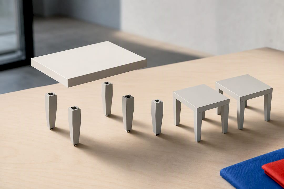
There’s a real distinction between a shared family and a nested-only component. A shared family, marked as such in Family Category and Parameters, can be individually selected, scheduled, and tagged even while nested inside a host. A non-shared nested family effectively disappears into the host: it contributes geometry but can’t be scheduled or tagged on its own. If you need a leg count in your furniture schedule, that leg family needs to be shared.
Advanced family techniques from Autodesk cover linking nested parameters back to the host: you associate the nested leg’s Height parameter to the parent table’s Height parameter, so changing the table’s overall height in Family Types automatically pushes that value down into every nested leg instance. Without that link, you’d need to edit the leg height separately for every table type, which defeats most of the point of nesting in the first place.
A practical example: build one Leg family with a Type Catalog offering square, tapered, and turned profiles. Nest it into your table family four times, one per corner. Associate each nested instance’s Height and Width to the parent’s parameters. Now swapping every table in a project from square legs to turned legs is a single type change in the parent, not four manual swaps per table.
Nest for reuse and centralized editing, not just to reduce triangle count.
Mark a nested family as shared the moment you know it needs its own schedule line or tag.
Link nested parameters to host parameters before you ship the family, not after someone asks why the legs won’t resize.
How Do You Test and Flex a Revit Family Before Sharing It?
Flexing means pushing every parameter to different values inside the Family Types dialog and watching whether the geometry responds correctly, every time, with no warnings. It’s the single most reliable way to catch a broken constraint before it becomes someone else’s problem in a live project.
Open Family Types and run through each parameter individually, from its smallest realistic value to its largest, checking for warnings or visibly wrong geometry after each change.
Test combinations, not just single parameters. A width change that works fine alone can break once a height parameter is also pushed to an extreme.
Load the flexed family into a sandbox project and confirm it schedules with the correct fields populated, tags correctly, and cuts the way you’d expect in a section view.
If the family includes nested shared components, swap between nested types and confirm the swap propagates cleanly with no orphaned geometry.
Check visibility settings across detail levels (coarse, medium, fine) since geometry that looks right at one detail level sometimes vanishes or duplicates at another.
Autodesk’s own guidance on creating loadable families frames this testing phase as non-optional before a family goes anywhere near a shared library. A family that flexes clean in isolation but has never been loaded into an actual project is only half tested. Sign off on production use only once it’s passed both checks.
Why Do Revit Families Break, and How Do You Fix Them Fast?
Most family failures trace back to one of a handful of root causes, and common diagnosis points to the wrong template, unlocked geometry, or an over-reliance on imported CAD as the usual suspects. Fragile constraints, geometry locked to one specific dimension state instead of a flexible reference, cause the same kind of failure once someone flexes a parameter you never tested.
Family won’t flex correctly: check for geometry that’s dimensioned to a fixed number rather than locked to a reference plane.
Family loads but schedules wrong: recheck the category, since schedules pull fields based on what category the family was built under.
Geometry looks fine until you flex it: an unlocked sketch line is almost always the culprit.
Family depends on a traced CAD import: replace the trace with native Revit geometry before it goes anywhere near a shared library.
Rebuild rather than repair once you’ve patched the same constraint failure three times. Pro Tip: Before adding any family to a shared team library, flex it to its size extremes one more time. A family that only works at “normal” dimensions is a support ticket waiting to happen.
What Does S15Studio Recommend for Learning Revit Family Creation?
The learning path that actually sticks follows a specific order: build one simple standalone family first, then move to nested components once single-family logic feels automatic, then parameters and formulas, then worksharing once you’re building for a team rather than yourself. Skipping straight to nested, formula-driven families before the basics click is the most common mistake we see, and it usually means going back to relearn reference planes under time pressure.
S15Studio’s course structure maps directly onto that sequence. The beginner Revit introduction covers the Family Editor fundamentals this article walks through. The intermediate course picks up nesting and parameter formulas. The advanced masterclass tackles the automation and library-scale techniques that come after that.
Editorial Take: Why Most Family Tutorials Skip the Part That Actually Matters
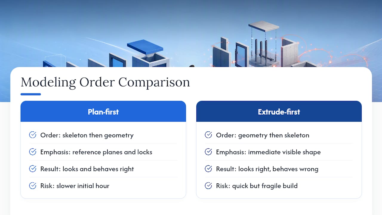
Most tutorials on this topic rush to geometry. Extrusion here, void cut there, done. That ordering is backward, and it’s the reason so many “finished” families quietly break the first time someone flexes a parameter they didn’t test. The reference plane skeleton isn’t a preliminary chore before the real modeling starts. It is the real modeling. Geometry is just the visible skin over decisions you already made when you named and locked those planes.
The conventional advice to “just start extruding and adjust later” produces families that look right and behave wrong, which is worse than a family that obviously doesn’t work, because the failure shows up downstream in someone else’s schedule or tag, far from where the mistake was made. If you take one thing from this guide, prioritize the plan-and-skeleton stage over the modeling stage. A slower first hour buys you a family that survives contact with a real project, and with a teammate who didn’t build it.
— Steve
Ready to Build Real Revit Skills Beyond This One Family?
This program helps you build working families faster than piecing it together from scattered tutorials and forum threads, because every course is structured around real projects instead of isolated feature demos. You get project files to work from, support when a constraint won’t cooperate, and a completion certificate once you’ve finished.
If you’re still getting comfortable with Revit’s basic interface and modeling tools, start with the Autodesk Revit introduction for beginners. Already building families but ready to tackle nesting, formulas, and shared parameters at scale? The complete Revit and AutoCAD training bundles that skill progression with certification exam practice. And if your next challenge is publishing families into a team-wide library without version conflicts, the Revit worksharing course picks up exactly where this article’s team strategies leave off. Check the course pages for what’s included and pick the one that matches where you actually are right now, not where you wish you were.
Where to Learn More About Revit Family Creation
The Autodesk University introduction to Revit families remains the clearest primary-source walkthrough of the full workflow, from template selection through flexing. Autodesk’s own Family Editor tools reference is worth bookmarking for quick lookups once you’re deep in a build and forget which tool does what. For a hands-on example with downloadable logic you can study line by line, BIMsmith’s parametric table tutorial shows nesting and formulas applied to a real, buildable object rather than an abstract example.
Sources
Recommended
Comments