
AutoCAD Regions Explained: A Design Professional's Guide


An AutoCAD Region is a 2D enclosed planar object created from closed loops of lines, polylines, arcs, circles, or splines. It behaves as a bounded area with physical properties, not just a visual outline. Three things you need to know right away:
Identify it: Select the object and check the Properties palette. A Region shows “Region” as its object type, not “Polyline” or “Line.”
Create it: Run the REGION command, select your closed geometry, and press Enter. AutoCAD converts the loop into a Region object and, by default, deletes the original source geometry.
Use it: Run MASSPROP on the Region to extract precise area, centroid, and moments of inertia. For a floor-plan polygon, this gives you a verified area figure in seconds, no manual calculation needed.
A quick example: draw a closed polyline representing a room boundary, convert it with REGION, then run MASSPROP. AutoCAD returns the exact area and centroid coordinates. That output is reliable enough to drop into a project report.
Note on terminology: “AutoCAD regional drawing” is a common search phrase, but the correct technical term is simply a Region object. S15studio’s AutoCAD training, led by Autodesk Certified Trainer Steve Fagan, covers Region workflows as part of its project-based curriculum.
Key Takeaways
An AutoCAD Region is a 2D planar object that stores area, centroid, and moments of inertia, making it the right choice whenever boolean operations or verified area reporting are required.
Point | Details |
What a Region is | A 2D enclosed planar object with physical properties like area and centroid, not just a visual boundary. |
When to use it | Use Regions for MASSPROP analysis, boolean operations (Union, Subtract, Intersect), and engineering-grade area reporting. |
Key commands | REGION, BOUNDARY, MASSPROP, UNION, SUBTRACT, INTERSECT, EXPLODE, PEDIT, JOIN. |
Critical pitfall | REGION deletes source geometry by default; set DELOBJ=0 before running the command. |
S15studio training | Steve Fagan’s project-based AutoCAD course covers Region workflows with real files and ACU certification prep. |
Table of Contents
What is an AutoCAD Region, and how does it differ from other objects?
A Region is a specific object class in AutoCAD (Autodesk). It stores area, centroid, and moments of inertia as part of its data. A closed polyline stores only geometry. That distinction matters the moment you need engineering-grade output.
Autodesk’s Region documentation confirms that Regions retain layer, linetype, and color from their source geometry but lose hatch associativity on creation. If your deliverable depends on associative hatching, keep the original polyline and re-apply hatch after converting.
When is a Region required rather than optional? Three scenarios:
MASSPROP analysis: centroid and moments of inertia are unavailable on polylines.
Boolean operations: Union, Subtract, and Intersect only work on Region objects.
Downstream engineering inputs: structural and MEP tools that consume 2D planar geometry with verified area properties expect Region-class objects.
Visual identification: open the Properties palette (Ctrl+1) and check the object type field. Alternatively, run MASSPROP and select the object. If AutoCAD returns area and centroid data, you have a Region. If it returns nothing, you have a polyline.
How do you create a Region in AutoCAD?
The sequence is: prepare geometry, close all loops, run REGION or BOUNDARY, then verify with MASSPROP. Before you start, set up your drawing template with correct units and confirm you are working in Model Space.
Check units and template. Open Drawing Units (type UNITS) and confirm the unit system matches your project. A mismatch here corrupts every area output downstream.
Audit geometry. Run AUDIT to catch corrupt objects, then ZOOM to inspect boundary intersections visually. Every loop must be fully closed with no gaps.
Close open segments. Use PEDIT > Join or JOIN to close near-miss gaps. For complex geometry, run BOUNDARY first. It generates a clean closed polyline from a picked internal point, which you can then convert.
Set DELOBJ. Type DELOBJ and set it to 0. This tells AutoCAD to keep the original geometry after Region creation. Skip this step and your source lines disappear.
Run REGION. Type REGION, select the closed loop(s), press Enter. AutoCAD reports how many Regions were created. If the count is lower than expected, one or more loops failed.
Verify. Select the new Region, open Properties, and confirm the object type. Then run MASSPROP and check that area and centroid values look correct for your geometry.
Pro Tip: Copy your source geometry to a locked backup layer before running REGION, even with DELOBJ set to 0. System variable states can change between sessions, and a backup layer costs nothing.
If REGION rejects a loop, the boundary likely has a self-intersection or a gap. Use BOUNDARY as the fallback: pick a point inside the intended area and AutoCAD traces a clean closed polyline. Convert that polyline with REGION.
How do boolean operations work on Regions?
Regions support boolean operations that work reliably for planar geometry, letting you combine, cut, and isolate areas with precision that manual editing cannot match.
Union: combining room areas. You have two adjacent room polygons, each converted to a Region. Run UNION, select both, press Enter. AutoCAD merges them into one Region. Run MASSPROP and you get the combined floor area instantly. Useful for open-plan area schedules.
Subtract: cutting door and window openings. Start with a floor slab Region. Create Regions for each door and window opening. Run SUBTRACT, select the slab Region first, press Enter, then select the opening Regions, press Enter. The openings are removed from the slab. The result is a net slab area ready for material takeoff.
Intersect: finding overlap zones. You have a site grading boundary and a building footprint, both as Regions. Run INTERSECT and select both. AutoCAD keeps only the overlapping area. This is useful for calculating how much of a footprint falls within a specific grading zone.
A few things to watch:
All Regions must be coplanar. If objects were created on different Z elevations, boolean ops will fail silently or produce unexpected results.
Self-intersecting Regions cause failures. Run MASSPROP on each Region individually before combining to confirm they are valid.
After a Subtract or Intersect, the consumed Regions are deleted. Work on copies if you need the originals.
Where do Regions fit in real architectural workflows?
Regions are not a niche command. They slot into several tasks that architects and technicians handle on most projects:
Area schedules: convert room boundaries to Regions, run MASSPROP, and export the output to a spreadsheet. Faster and more accurate than manual area tags.
Massing sketches: use Union to combine floor plate Regions across levels for gross area calculations.
Hatch boundaries: define complex hatch zones as Regions, apply hatch, then re-apply if the Region changes. Note that hatch associativity is lost on Region creation, so plan for manual re-hatch.
2D profiles for extrusion: Regions are the preferred input for EXTRUDE in 3D modeling workflows.
Precise cutouts: Subtract openings from slabs or ceilings for net area and material quantities. This feeds directly into quantity measurement workflows used by estimators.
Engineering inputs: export MASSPROP results to a text file for structural or MEP engineers who need verified centroid and moment data.
Presentation graphics: shade Regions with solid fills for clean plan graphics without relying on hatch patterns.
Use case | Key commands | Verification |
Area reporting | REGION, MASSPROP | Check area matches known dimension |
Opening cutouts | REGION, SUBTRACT | MASSPROP net area |
Massing totals | REGION, UNION | MASSPROP combined area |
3D profile prep | REGION, EXTRUDE | Visual check in 3D view |
Hatch zones | REGION, HATCH | Visual check, re-hatch after edit |
What CAD standards should govern Region use on a project?
Adopt a short set of rules for Regions and enforce them through templates and QA checks. Ad hoc Region use creates files that are hard to audit and harder to hand off. Structured drafting habits reduce errors and make Region creation repeatable across a team.
Eight rules worth adopting:
Dedicated layer: place all Regions on a layer named A-AREA-REGION or equivalent per your firm’s layer standard. Never leave Regions on layer 0.
DELOBJ in template: set DELOBJ=0 in your project template so every session preserves source geometry by default.
Backup geometry: copy source loops to a locked _BACKUP layer before conversion.
Naming convention: if your workflow uses attributes or scripts, name Region-bearing layers consistently so automation can target them.
Re-hatch rule: document in your QA checklist that any Region edit requires manual hatch reapplication.
Change log: note boolean operations in the drawing’s revision history, especially Subtract operations that remove geometry permanently.
MASSPROP export: save MASSPROP text output to a project folder alongside the DWG for engineer verification. Engineering drawing best practices support this as a verification step.
Vocabulary in standards: explicitly define “Region” in your CAD standards document. Teams confuse the AutoCAD Region object with geographic or agency-level “regional” drafting standards. Design & Motion’s Region deep-dive flags this as a recurring team confusion worth addressing directly.
Pro Tip: Store your Region-creation sequence as a short LISP routine or Action Macro. A five-step macro that sets DELOBJ, runs REGION, and opens MASSPROP saves time and eliminates the most common setup errors on every use.
How do you fix common Region creation errors?
The most common causes of failure are open loops, self-intersections, layer or linetype issues, and DELOBJ surprises. Most problems resolve with three commands: BOUNDARY, PEDIT, and AUDIT.
Common errors and fixes:
“0 regions created”: the loop has a gap. Use PEDIT > Join or JOIN to close it, or use BOUNDARY to trace a clean polyline.
Self-intersection rejection: the boundary crosses itself. Zoom in and manually correct the crossing segment, then retry REGION.
Source geometry deleted unexpectedly: DELOBJ was set to 1. Undo (Ctrl+Z), set DELOBJ=0, and rerun REGION.
MASSPROP returns no data: the selected object is not a Region. Check the Properties palette. If it shows “Polyline,” convert it first.
Non-coplanar curves: objects were drawn at different Z values. Use FLATTEN or manually set all Z coordinates to 0 before running REGION.
Corrupt geometry: run AUDIT then PURGE. Corrupt objects can prevent Region creation without a clear error message.
Quick command reference:
Problem | Commands to try |
Open loop | JOIN, PEDIT > Join, BOUNDARY |
Self-intersection | Zoom + manual edit, BOUNDARY |
Source geometry lost | UNDO, set DELOBJ=0, rerun REGION |
Non-coplanar curves | FLATTEN, then REGION |
Corrupt objects | AUDIT, PURGE |
Revert Region to lines | EXPLODE |
When a Region fails, the workflow is: diagnose with MASSPROP and Properties, repair with JOIN or BOUNDARY, then recreate with REGION. If the geometry is genuinely complex, use BOUNDARY to generate a clean polyline first. The AutoCAD-LT ActiveX Reference documents how AddRegion handles loop conversion programmatically, which is useful context if you are scripting Region creation in a batch workflow.
Why Regions are worth the learning curve
Most AutoCAD users spend years drawing closed polylines and never touch the REGION command. That is a missed opportunity. Regions are where 2D drafting crosses into geometric modeling. The boolean operations alone, Union, Subtract, Intersect, replace hours of manual editing with three commands. The MASSPROP output replaces error-prone manual area calculations with verified data you can hand to an engineer without qualification.
The caveat: Regions are not always the right tool. If your deliverable is strictly hatch-based and associativity matters more than mass properties, keep the polyline. If the project moves to 3D, switch to solids. Regions live in the space between basic drafting and full 3D modeling, and that space covers a large portion of what architects and technicians actually produce day to day.
S15studio AutoCAD training covers Region workflows in depth
Knowing the REGION command is one thing. Knowing when to use it, how to set up the file correctly, and how to troubleshoot it on real project geometry is another. S15studio’s complete AutoCAD training covers Region creation, boolean operations, and MASSPROP reporting as part of a project-based curriculum built by Autodesk Certified Trainer Steve Fagan. You get downloadable templates with DELOBJ pre-configured, practice files with real architectural geometry, and direct trainer support.
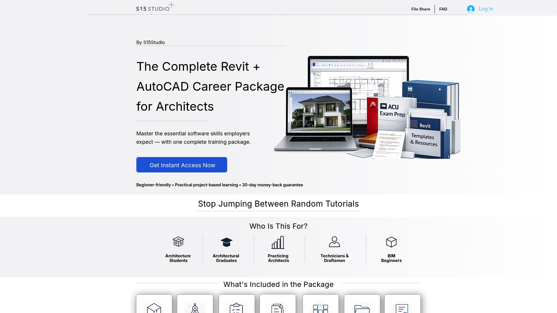
The course path runs from foundational drafting through advanced workflows, with certification prep for the Autodesk Certified User (ACU) exam built in. If you want structured practice rather than trial and error, the full Revit and AutoCAD training bundle is the most direct route to professional-level competency.
Sources
Recommended
Comments