
Revit Load-Bearing Walls: Identify, Create, and Manage
- Steve Fagan

- 4 days ago
- 9 min read

A load-bearing wall in Revit is a wall instance with its Structural parameter enabled and its Structural Usage set to Bearing (or another structural role). That’s the definition. Two things to do right now in your model:
Open any wall’s Properties palette, check that Structural is toggled on, and confirm Structural Usage reads Bearing rather than Non-bearing.
For walls that need to feed a structural analysis, place them with Structure > Wall: Structural from the start rather than converting later.
Those two steps cover most of what goes wrong on real projects. The rest of this guide explains the parameters in depth, walks through creation and conversion workflows, and gives you a coordination checklist built around Autodesk Revit’s own documentation.
Key Takeaways
A Revit load-bearing wall is defined by two instance parameters: Structural (enabled) and Structural Usage (set to Bearing or another structural role), not by its material or wall type.
Point | Details |
Two parameters define bearing status | Enable Structural and set Structural Usage to Bearing on each wall instance. |
Use the Structural Wall tool for analysis | Structure > Wall: Structural sets analytical model data automatically; Architecture > Wall does not. |
Instance-level, not type-level | Two walls of the same type can have different Structural Usage values; audit by schedule, not by type. |
Stacked walls need individual checks | Convert and validate each sub-wall segment separately before exporting the analytical model. |
S15studio for hands-on practice | The Intermediate and Master Class courses cover structural wall workflows in a project-based format. |
Table of Contents
What is a Revit load-bearing wall? Key parameters explained
In structural terms, a load-bearing wall supports vertical loads above it and transfers them down to the foundations. The defining criterion is the load path, not the material. A concrete wall with no Structural designation in Revit is still architecturally classified as non-bearing as far as the software is concerned.
Revit tracks bearing status through two instance parameters:
Parameter | Type | What it controls |
Structural | Instance (checkbox) | Whether the wall participates in the structural model at all |
Structural Usage | Instance (dropdown) | The structural role: Non-bearing, Bearing, Shear, or Structural Combined |
Analytical Model | Instance (checkbox) | Whether the wall exports geometry for structural analysis |
Structural is the master switch. Without it enabled, Structural Usage is irrelevant. Structural Usage then defines the role. Because both are instance properties, two walls of the same type can carry different structural classifications, which is powerful but also a common source of auditing headaches.
Find these in the Properties palette when a wall is selected. They do not live in the Type Properties dialog, so editing the type won’t change bearing status across a project. Per Autodesk Help, Structural Usage defaults differ depending on which placement command you used: Architectural walls default to Non-bearing, Structural walls default to Bearing.
How to create a structural wall the right way
The cleanest path to an analysis-ready bearing wall is to use the dedicated Structural Wall tool from the start. Autodesk Learn recommends this workflow because it sets the analytical model data automatically, which saves correction time before export.
Go to Structure > Wall: Structural (not Architecture > Wall).
In the Type Selector, choose an appropriate wall type: concrete, CMU, or a framed assembly. Confirm the type name matches your project naming convention before placement.
In the Properties palette, verify Structural Usage is set to Bearing and that Analytical Model is enabled.
Set Base Constraint, Base Offset, Top Constraint, and Top Offset before drawing. Walls with unconnected heights can cause analytical model gaps.
Draw the wall in plan view or a 3D view. Check wall joins at corners immediately after placement.
Link the wall to its foundation element (a structural foundation wall or isolated footing) to complete the load path in the model.
Pro Tip: Before placing any structural wall, align your analytical reference settings. Walls default to centerline; beams may reference the core face. Mismatched analytical references create gaps in the exported model that structural engineers have to fix manually.
If a structural wall doesn’t appear in a structural plan view after placement, check two things: the view’s Discipline setting (it should be Structural or Coordination) and the wall’s Structural parameter. A wall placed via the Architectural tab with Structural toggled off will be invisible in a discipline-filtered structural view.
How to convert an existing architectural wall to load-bearing
Converting is straightforward, but a few edge cases can trip you up.
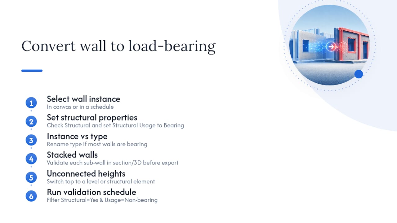
Select the wall instance in the canvas or a schedule. In the Properties palette, check Structural and set Structural Usage to Bearing. That’s the core action. Because Structural Usage is an instance property, this change affects only the selected wall, not every wall of that type across the project.
When to convert instances vs. rethinking the type: If most walls of a given type are bearing, consider whether the type name should reflect that. Naming a type “Concrete Block 200mm Bearing” versus “Concrete Block 200mm” makes auditing faster. The type name is a label, not a structural designation, but clear naming prevents confusion during coordination.
Stacked walls need extra care. A stacked wall is a compound element made of sub-wall instances stacked vertically. Converting the stacked wall host doesn’t automatically convert each sub-wall segment. SDC Publications’ Revit structural fundamentals material flags this specifically: validate each segment individually and test the result in a section or 3D view before exporting the analytical model. Getting this wrong produces broken analytical geometry that’s tedious to untangle.
Unconnected heights are another issue. A converted wall with an unconnected height rather than a constraint-based top may not align with the floor or roof above in the analytical model. After conversion, switch the top constraint to a level or structural element rather than leaving it as an unconnected height.
Pro Tip: After converting a batch of walls, run a wall schedule filtered by Structural = Yes and Structural Usage = Non-bearing. Any result in that schedule is a mismatch that needs attention before the model goes to the structural engineer.
The four Structural Usage options and when to use each
Autodesk Help confirms that Structural Usage is an instance-level setting with four options:
Non-bearing: The wall carries no structural load. Use this for partition walls, cladding, and interior dividers. Walls placed via the Architecture tab default here.
Bearing: The wall supports vertical loads from floors, roofs, or other walls above. This is the standard setting for load-bearing walls and the one most structural coordination workflows expect.
Shear: The wall resists lateral forces (wind, seismic) rather than primarily vertical loads. Concrete or masonry shear walls in a lateral system get this designation.
Structural Combined: The wall performs both bearing and shear functions simultaneously. Use this for walls that carry gravity loads and are part of the lateral system.
The choice directly affects documentation outputs. Structural Usage drives how walls appear in schedules, what gets exported to analysis tools, and how view filters sort elements on structural sheets. Setting Non-bearing on a wall that is actually carrying a floor beam above it won’t cause Revit to warn you; the error shows up later when the structural engineer’s analysis model is missing a wall.
Structural Usage | Primary function | Typical example |
Non-bearing | No structural load | Interior partition, curtain wall infill |
Bearing | Vertical load transfer | Exterior masonry wall below floor slab |
Shear | Lateral load resistance | Concrete core wall in a high-rise |
Structural Combined | Vertical + lateral | Perimeter concrete wall in a low-rise |
Why non-load-bearing walls sometimes appear in structural views
Setting a view’s Discipline to Structural hides walls whose Structural parameter is off. This is the fastest way to clean up a structural plan. But it’s a blunt instrument: it hides all non-structural elements, not just non-bearing walls.
For more control, build a View Filter. Go to View > Filters > Edit/New, create a filter for the Wall category, and set the rule to Structural Usage does not equal Bearing (or test the Structural parameter directly). Apply a color override or a hide rule to that filter. Apply the filter to a view template so every structural sheet in the project inherits the same logic automatically.
Pro Tip: A view template that includes a bearing-wall filter and a color override (say, red for bearing, gray for non-bearing) lets any team member open a structural plan and immediately read the structural system. It takes about ten minutes to set up and saves hours of verbal coordination.
Visibility problems with Revit project parameters and schedules are a related issue: if your schedule isn’t showing the Structural or Structural Usage fields, add them via Fields in the schedule properties. That schedule becomes your audit tool.
Does Revit calculate structural loads?
Revit stores an analytical model and can export it, but it does not perform full structural calculations on its own. The distinction matters.
What Revit does:
Maintains analytical model geometry (centerlines, references, connectivity) for walls, floors, beams, and columns.
Exports that geometry to analysis tools via formats like IFC or direct links to Autodesk structural analysis products.
Supports structural analysis workflows through plugins and interoperability with third-party software.
What Revit does not do:
Run load calculations or produce a structural engineer’s calculation report.
Validate whether a bearing wall is adequately sized for the loads above it.
Replace code compliance review.
Per the Novedge blog’s guidance on structural load management in Revit, full structural calculations belong in dedicated analysis software. Revit prepares and organizes the data; the engineer runs the numbers. Treating a clean Revit analytical model as a substitute for structural calculations is a coordination risk, not just a modeling one.
Common mistakes and best practices for bearing walls
Most structural coordination problems trace back to a handful of repeated errors. Here’s what to check before any model handoff, based on Autodesk Certified Trainer guidance.
Checklist before structural handoff:
Audit all wall instances with a schedule showing Structural and Structural Usage fields. Look for walls that should be bearing but aren’t flagged.
Verify analytical model alignment: wall analytical references (centerline vs. core face) should match the reference convention used for beams and columns. Misaligned references create gaps in the exported model.
Confirm wall type names reflect structural intent where possible. “Conc Wall 200mm Bearing” is faster to audit than “Basic Wall 12.”
Check base and top constraints on all structural walls. Unconnected heights are a common source of analytical model errors.
Use worksharing coordination comments to flag walls that have been converted or reclassified since the last handoff.
Common mistakes:
Assuming material implies structural behavior. A concrete wall placed via the Architecture tab is Non-bearing until you change it. SDC Publications’ training material makes this point directly: material and structural designation are independent in Revit.
Setting Structural Usage at the type level when instance-level differences exist. Since Structural Usage is an instance property, type-level thinking leads to missed classifications.
Ignoring analytical model misalignment until the structural engineer reports errors. Fix it in Revit before export.
Skipping the stacked wall check. See the conversion section above.
For a broader look at modeling mistakes to avoid in Revit, the pattern is consistent: classification errors that seem minor in early design create expensive rework in coordination and documentation.
Pro Tip: Set a brief handoff routine with your structural engineer: agree on which wall types are included in the handoff model, what analytical model checks you’ve run, and what naming convention you’re using. A one-page checklist shared before the first handoff prevents most of the back-and-forth.
For teams using worksharing, the Revit worksharing course at S15studio covers the coordination workflow in detail, including how to manage structural elements across worksets.
The case for getting structural walls right from the start
The convert-later approach is common on real projects. Teams model fast in early design, then clean up structural designations before coordination. That works if you have a strict auditing routine and someone who actually runs the schedule check before handoff.
What I’ve seen in training is that the audit step gets skipped under deadline pressure. The structural engineer opens the model, finds a dozen walls with Non-bearing status that should be Bearing, and the project loses half a day to corrections that could have been avoided. Placing walls with the Structural Wall tool from the start costs maybe thirty seconds per wall. The conversion audit costs thirty minutes per model, minimum, and that’s when nothing is wrong.
The analytical model alignment issue is the one most architects underestimate. It looks fine in Revit. The structural engineer’s analysis software sees gaps and disconnected nodes. Aligning analytical references before export is a five-minute check that prevents a two-hour email thread.
S15studio Revit courses for hands-on structural wall practice
Knowing the parameters is one thing. Working through a real project model is where the workflow actually sticks.

S15studio’s Revit Beginner to Intermediate course covers the Structural Wall tool, instance parameters, and view filter setup in a project-based format, so you practice the exact steps in this article on a real model rather than a demo file. For teams who need the full coordination workflow including analytical model export and worksharing, the Revit Master Class goes from beginner to advanced with direct trainer support and lifetime access to materials. Both courses include downloadable notes and completion certificates. Pick the level that matches where you are now and work through the structural wall units before your next project handoff.
Sources
Recommended
Comments