
Create AutoCAD Linetypes in 10 Minutes for Architects and Drafters


Creating a custom linetype in AutoCAD comes down to two moves: define the pattern, then load it. You write the definition either by editing a plain-text .LIN file with A-type alignment syntax or by generating one through Express Tools (MKLTYPE and MKSHAPE). Once saved, you load it into the active drawing with the LINETYPE command before it appears anywhere on a layer.
TL;DR:
Loading the new linetype using the LINETYPE command is essential; otherwise, the pattern will not appear in the drawing despite correct syntax.
Complex linetypes with embedded shapes or text require supporting .SHX files to be in the support path; missing files often cause patterns to render as gaps or blanks.
Proper scale adjustment is crucial; use LTSCALE and CELTSCALE, and run REGEN to ensure dash patterns display correctly in both model and plot views.
Errors such as vanished patterns or pattern misalignments typically stem from syntax mistakes or missing support files, not from the .LIN file content alone.
Testing complex linetypes in a separate, clean drawing helps identify scaling or alignment issues before applying them in live projects.
Table of Contents
Quick Checklist for Custom Linetype Creation in AutoCAD
Before touching syntax, run through the sequence that gets a working linetype on screen in under ten minutes.
Pick your method. Open a .LIN file in a text editor for a simple dash pattern, or launch Express Tools if you need embedded text or shapes.
Write the two-line definition. Line one names the linetype; line two starts with A and lists the pattern descriptors.
Save the .LIN file, then open the LINETYPE dialog (or type -LINETYPE) and choose Load to pull the new definition into your drawing.
Assign it to a layer or directly to objects, then check the display.
Fix scale issues by adjusting LTSCALE or CELTSCALE and running REGEN if dashes look continuous or missing.
Remember complex linetypes need supporting .SHX shape or font files sitting in a path AutoCAD can actually find, or the pattern renders as blank space.
Miss step three and nothing changes, no matter how correct your syntax is. AutoCAD does not autoload a linetype just because you saved the file.
Create a Simple Linetype by Editing a .LIN File
Every linetype definition, no matter how basic, follows the same two-line structure. Line one starts with an asterisk, followed by the name and an optional description. Line two starts with the letter A, which flags A-type alignment — the setting that forces every line, arc, and polyline segment to begin and end on a dash rather than a gap. That alignment rule is why architectural linetypes look clean at corners instead of trailing off into empty space.
After the A, you list pattern descriptors separated by commas. A positive number draws a dash of that length. A negative number draws a gap. Zero draws a dot. AutoCAD allows up to 12 descriptors per definition, which is more than enough for anything short of a decorative border pattern.
*FENCELINE, Fence line —o—o—o— A,.5,-.25,0,-.25
That two-line block draws a half-unit dash, a quarter-unit gap, a dot, and another quarter-unit gap, repeating for the length of the line. It’s a real, working .LIN definition you can paste directly into a text file.
Most installs keep the standard linetype library in acad.lin (imperial) or acadiso.lin (metric), typically inside the Support folder of your AutoCAD installation. You can append new definitions to either file or build a dedicated project-specific .LIN file, which is usually the cleaner move for firm-wide standards.
Prefer the command line? Type -LINETYPE and AutoCAD walks you through creating or appending a definition without ever opening a text editor, which is handy for a quick one-off pattern mid-drawing.
Building Complex Linetypes with Text or Shapes
Simple dash-and-gap patterns cover most drafting needs, but property lines, utility runs, and demolition markers often call for embedded text or symbols. That’s where MKLTYPE and MKSHAPE come in. MKSHAPE captures selected geometry and compiles it into a .SHX shape file; MKLTYPE then references that shape inside a new linetype definition and writes the finished code to your chosen .LIN file.
A shape-based descriptor looks like this inside the .LIN file: [GAS,gasline.shx,S=0.5,U=0,X=0,Y=-0.05]. The bracket holds the shape name, the source .SHX file, and modifiers for scale (S), rotation or upright angle (U/R/A), and X/Y offset from the line.
A few things trip people up constantly:
Text height: set the text style height to 0, not a fixed value, or scale changes will distort spacing unpredictably.
The U flag: use the upright flag so embedded text stays readable regardless of line direction.
Color: complex linetypes render in a single color, either ByLayer or a fixed value baked into the definition. You cannot mix colors within one pattern.
Explodability: embedded shapes and text inside a complex linetype cannot be exploded into separate objects.
Platform limits: Express Tools don’t exist in AutoCAD LT or in some Mac builds, so those users need to write .LIN and .SHX code manually.
Pro Tip: Build and test complex linetypes in a blank scratch drawing first. Scale and alignment errors are far easier to spot on a clean canvas than buried inside a live project file.
Loading and Controlling Linetype Scale in AutoCAD
Writing the definition is only half the job. AutoCAD requires you to load the linetype into the current drawing through the LINETYPE command, or -LINETYPE at the command line, choosing Load and pointing to your .LIN file. Skip this step and the definition sits unused on disk no matter how many times you save it.
Two variables control how the pattern actually looks on screen:
LTSCALE sets the global scale factor for every linetype in the drawing. Bump it up and dashes stretch; drop it and they shrink, which matters most on large-format architectural sheets.
CELTSCALE scales an individual object’s linetype independent of LTSCALE, useful when one dimension line or annotation needs a different dash rhythm than the rest of the drawing.
If dashes appear as a solid line after loading, run REGEN. AutoCAD sometimes needs that manual refresh to redraw the pattern correctly, especially after changing scale variables. Polylines can behave oddly with complex linetypes unless PLINEGEN is set to 1, which controls whether the pattern generates continuously around vertices instead of resetting at each segment.
Screen display and plotted output don’t always match. Always check a print preview or plot a test sheet before finalizing scale, since some plot styles and lineweights compress dash spacing differently than the model space view suggests.
Fixing Common Linetype Problems and Sharing Files
Most linetype headaches trace back to one of three causes: a missing support file, a syntax typo, or an overwritten definition.
Shapes showing as blank gaps or a placeholder symbol almost always mean the .SHX file referenced in your complex linetype isn’t on AutoCAD’s support file search path. Copy the .SHX alongside the drawing or add its folder to Options → Files.
Definitions vanishing after an edit usually happen because someone overwrote rather than appended a .LIN file. Back up acad.lin or your project .LIN before editing it.
Patterns that won’t load at all typically come down to a syntax mistake: a missing comma, an incorrect descriptor count, or a second line that doesn’t start with A.
When sharing a drawing with a custom linetype, always include both the .LIN file and any referenced .SHX files, not just the DWG itself. Recipients without those files simply won’t see your pattern, even if the linetype name still appears correctly in their layer list.
Why Practical Training Beats Trial-and-Error Linetype Editing

I’ve watched plenty of talented drafters burn an afternoon on a linetype that should have taken ten minutes, usually because nobody showed them the difference between A-type alignment and the older style, or when Express Tools actually save time versus when manual .LIN editing is faster.
Architects tend to reach for Express Tools first because MKLTYPE and MKSHAPE feel visual and immediate. CAD drafters managing firm-wide standards often prefer hand-editing .LIN files, since it’s easier to version-control a text file and keep naming consistent across projects. Neither approach is wrong. Knowing which one fits the job in front of you, and which one your license even supports, is the skill that actually saves time. It also pairs naturally with solid drawing standards for how you name and organize custom linetypes across a project.
— Steve
Learn AutoCAD Workflows the Structured Way with S15studio
Piecing together linetype syntax from scattered help articles works, eventually, but it’s a slow way to build real drafting fluency. S15studio’s AutoCAD training program covers linetype management alongside the drafting standards, layer conventions, and plotting workflows architects and technicians use daily on real projects. You get hands-on practice projects instead of guesswork, plus direct trainer support when a pattern or scale setting isn’t behaving the way the documentation says it should.
The course also folds in certification prep, so the skills you’re building double as exam readiness if you’re working toward an Autodesk Certified User credential. If you’re tired of relearning the same syntax every few months, start with the full AutoCAD course and put the fundamentals to work permanently.
Where to Verify Linetype Syntax and Build Patterns Faster
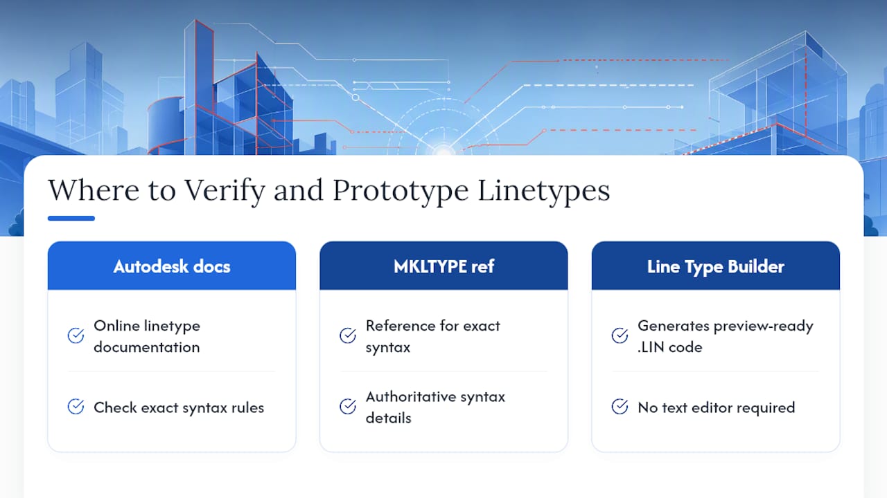
Cross-check anything unusual against Autodesk’s linetype documentation and the MKLTYPE reference for exact syntax. For quick prototyping, the AutoCAD Line Type Builder generates preview-ready .LIN code without opening a text editor.
Sources
Recommended
Comments