AutoCAD 3D Solid Modeling Workflow: 2026 Guide
- Steve Fagan

- 5 days ago
- 8 min read

The AutoCAD 3D solid modeling workflow is the structured sequence of steps, from template configuration through Boolean operations and layer management, that separates professional-grade 3D models from geometry that fails in production. Design professionals and architectural technicians who skip this structure spend hours fixing errors that a disciplined process would have prevented entirely. The core tools in this workflow include AutoCAD’s EXTRUDE, REVOLVE, UNION, SUBTRACT, and INTERSECT commands, supported by OVERKILL for profile cleanup and .DWT template files for environment consistency. Getting these steps right from the start is what drives both accuracy and project efficiency.
What does a structured AutoCAD 3D solid modeling workflow look like?
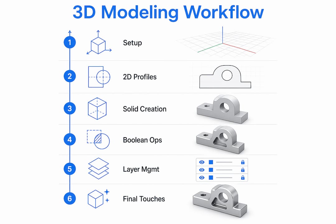
A structured AutoCAD 3D solid modeling workflow follows a clear sequence: environment setup, 2D profile preparation, solid creation, Boolean operations, layer organization, and final validation. Each stage feeds the next. Skipping profile cleanup before EXTRUDE, for example, produces broken solids that fail Boolean operations downstream. The industry term for this approach is a parametric solid modeling workflow, though AutoCAD’s implementation is history-based rather than fully parametric like Autodesk Inventor or Fusion 360. Knowing that distinction helps you plan your modeling sequence correctly from the start.

How to set up your AutoCAD environment for 3D solid modeling
The foundation of any reliable 3D modeling process in AutoCAD is a properly configured environment. A custom .DWT template file is the first thing to create. Templates embed your layer structure, object snap settings, plotting configurations, and visual styles into one reusable file, eliminating setup inconsistencies across projects.
A well-built template for 3D solid modeling should include:
Layers with assigned colors, linetypes, and lineweights for solids, construction geometry, dimensions, and annotations
Object snaps set to Endpoint, Midpoint, Intersection, and Perpendicular as defaults
Visual style set to Conceptual or Realistic for 3D work, with Wireframe available for editing
Grid and snap configured for your typical working scale
Plot styles attached and tested before any project work begins
Template files unify project standards by embedding all of these settings in one place. That means every drawing you open starts from the same baseline, which matters enormously when multiple technicians work on the same project.
Pro Tip: Save your template to a shared network location and set AutoCAD’s default template path in Options to point there. Every new drawing will open with your firm’s standards already in place.
Plot configuration deserves as much attention as the drawing itself. Mismatched lineweights or incorrect plot styles in final prints undermine the accuracy of the model you spent hours building.
Why does 2D profile quality affect 3D solid creation?
Dirty 2D geometry is the most common cause of failed EXTRUDE and REVOLVE operations in AutoCAD. A profile with overlapping lines, tiny gaps, or duplicate segments looks clean on screen but breaks solid generation at the kernel level. The fix is the OVERKILL command, which removes overlapping geometry and duplicates before you attempt any 3D operation.
The correct preparation sequence before creating any solid:
Draw or import your 2D profile
Run OVERKILL with default settings to remove duplicates and merge overlapping segments
Use PEDIT or JOIN to close any open gaps in the profile boundary
Verify closure with the BOUNDARY command, which only succeeds on fully closed profiles
Confirm the profile lies on a flat plane before running EXTRUDE or REVOLVE
Common errors caused by skipping this process include solids that appear correct in Conceptual view but fail UNION or SUBTRACT operations. AutoCAD’s solid kernel cannot process geometry with self-intersections or open loops. Spending two minutes on profile cleanup saves thirty minutes of troubleshooting later.
Pro Tip: After running OVERKILL, zoom in to corners and intersections at 1:1 scale. Gaps smaller than your current snap tolerance are invisible at normal zoom levels but will still cause EXTRUDE to fail.
What are the best practices for Boolean operations in AutoCAD 3D?
Boolean operations, specifically UNION, SUBTRACT, and INTERSECT, are where most AutoCAD solid modeling errors occur. Staging these operations logically is the single most effective way to prevent model corruption. The correct order is to union large base components first, then subtract detail cuts, then apply intersections for complex shared volumes.
Key rules for reliable Boolean operations:
Convert geometry first. Use CONVTOSOLID to convert any surfaces or meshes to solids before running UNION or SUBTRACT. Mixed geometry types cause Boolean failures every time.
Avoid coplanar faces. When two solids share an exact face, AutoCAD cannot determine which geometry takes priority. Add a slight overlap of 1–2mm instead of aligning faces exactly flush.
Keep a pre-Boolean copy. Store a backup copy of your components on a non-plot layer before running any Boolean. If the operation fails or produces unexpected geometry, you can restore without rebuilding from scratch.
Use INTERFERE to validate. Run the INTERFERE command to check for unintended overlaps between solids before committing to UNION or SUBTRACT.
Use SLICE for complex cuts. SLICE gives you more control than SUBTRACT for planar cuts through existing solids.
Deferring fillets and chamfers until the final stages of your model avoids increasing kernel complexity and prevents subsequent Boolean operations from failing. Edge treatments applied too early create additional faces and edges that the Boolean kernel must reconcile, which multiplies the chance of calculation errors.
This sequencing discipline is what separates technicians who finish models cleanly from those who rebuild the same geometry three times.
How does layer management affect your 3D modeling results?
Disciplined layer management directly controls printing accuracy and editing efficiency in complex 3D models. Assigning each solid or component type to a dedicated layer gives you the ability to isolate, hide, or lock geometry without affecting the rest of the model. This becomes critical on architectural projects where structural, mechanical, and finish elements all occupy the same file.
A practical layer structure for 3D solid modeling looks like this:
Layer name | Purpose | Lineweight | Plot |
SOLID-STRUCTURE | Load-bearing elements | 0.50mm | Yes |
SOLID-FINISH | Cladding and surface materials | 0.25mm | Yes |
CONSTRUCTION | Reference geometry | 0.13mm | No |
PRE-BOOLEAN | Backup copies before operations | Default | No |
ANNOTATION | Dimensions and text | 0.18mm | Yes |
The PRE-BOOLEAN layer is non-negotiable on complex projects. It holds your backup copies and never plots, so it adds zero clutter to printed output. Use LAYMRG to merge redundant layers and PURGE to remove unused layer definitions before issuing any drawing for review. Both commands keep file size manageable and reduce confusion for collaborators.
Troubleshooting common issues in your AutoCAD 3D workflow
Boolean operation failures and selection errors are the two most frequent problems in AutoCAD 3D solid modeling. Most failures trace back to geometry issues that OVERKILL and CONVTOSOLID would have caught earlier in the process. If a Boolean fails after you have already cleaned your profiles, the next step is to check for non-manifold conditions, which are edges shared by more than two faces, using the SOLIDEDIT command to identify problem areas.
Practical fixes for the most common issues:
Selection errors in dense assemblies. Enable SELECTIONCYCLING by pressing Shift+Space or setting the SELECTIONCYCLING variable to 2. This lets you cycle through overlapping solids and pick the correct one without moving geometry.
Slow visual performance. Reduce the FACETRES variable from its default to a lower value for working views. Increase it only when generating presentation renders.
Repeated Boolean failures. Explode the problem solid, re-close the profile with PEDIT, and rebuild using EXTRUDE. This resolves most non-manifold conditions faster than trying to repair the solid directly.
Workflow automation. Use AutoCAD’s Action Recorder to capture repetitive sequences like layer switching, OVERKILL, and view changes. Assign these macros to keyboard aliases in the PGP file for one-keystroke access.
Pro Tip: Create a custom command alias in your ACAD.PGP file that runs OVERKILL followed by BOUNDARY in sequence. Running both commands takes under ten seconds and catches profile errors before they reach the solid creation stage.
Key takeaways
A reliable AutoCAD 3D solid modeling workflow requires disciplined setup, clean geometry, staged Boolean operations, and organized layer management working together at every stage.
Point | Details |
Start with a .DWT template | Embed layers, snaps, and plot styles in one file to keep all projects consistent. |
Run OVERKILL before every solid | Clean 2D profiles prevent EXTRUDE and REVOLVE failures before they start. |
Stage Boolean operations logically | Union large parts first, then subtract details, and always keep a pre-Boolean backup layer. |
Defer fillets and chamfers | Apply edge treatments only after all Boolean operations are complete to avoid kernel errors. |
Use SELECTIONCYCLING in dense models | Cycling through overlapping solids prevents accidental edits to the wrong geometry. |
What I have learned from years of AutoCAD 3D solid modeling
The biggest mistake I see design professionals make is treating the AutoCAD 3D environment like a 2D drafting space with depth added. They jump straight into EXTRUDE without a template, without cleaning profiles, and without any layer structure. Then they wonder why their Boolean operations fail or why the model looks correct on screen but prints incorrectly.
The workflow discipline I have described here is not theoretical. Every step, from the .DWT template to the PRE-BOOLEAN layer, comes from watching what goes wrong when those steps are skipped. The OVERKILL command alone has saved more project hours than any other single habit I have built into my process. Most technicians discover it only after spending an afternoon troubleshooting a solid that refuses to subtract correctly.
My honest advice is this: build the workflow before you build the model. Spend thirty minutes configuring your template correctly, and that investment pays back on every project you open afterward. AutoCAD rewards process. The professionals who get consistent, accurate results are not necessarily faster modelers. They are more disciplined ones. If you want to go deeper on AutoCAD and Revit as professional tools, the fundamentals of workflow setup apply across both platforms.
— Steve
Take your AutoCAD 3D skills further with S15studio
S15studio was founded by Autodesk Certified Trainer Steve Fagan specifically to help architects and architectural technicians build real-world AutoCAD and Revit skills. The training goes beyond commands and covers the workflow thinking that makes professionals faster and more accurate on actual projects.

The Mastering AutoCAD course covers 3D solid modeling techniques, template setup, Boolean operations, and layer management in a structured, project-based format. For professionals who want to cover both platforms, the complete Revit and AutoCAD training program builds a full design workflow from the ground up. Both courses are built for working professionals who need skills they can apply immediately, not theory they have to translate themselves.
FAQ
What is the first step in an AutoCAD 3D solid modeling workflow?
The first step is creating a custom .DWT template file that embeds your layer structure, object snaps, visual styles, and plot configurations. This eliminates setup inconsistencies across every project you open.
Why do Boolean operations fail in AutoCAD 3D?
Boolean failures most often result from dirty 2D profiles, mixed geometry types, or coplanar faces between solids. Running OVERKILL on profiles and CONVTOSOLID on surfaces before any Boolean operation resolves the majority of these failures.
When should I add fillets and chamfers to a 3D solid model?
Add fillets and chamfers only after all Boolean operations are complete. Applying edge treatments earlier increases kernel complexity and causes subsequent UNION or SUBTRACT operations to fail.
What does SELECTIONCYCLING do in AutoCAD 3D?
SELECTIONCYCLING lets you cycle through overlapping or stacked solids in a dense assembly to select the correct object. It prevents accidental edits to the wrong geometry without requiring you to move or hide other solids first.
How do I recover from a failed Boolean operation in AutoCAD?
Restore the pre-Boolean backup copy stored on your non-plot layer, check the geometry for non-manifold conditions using SOLIDEDIT, and re-run the operation after correcting the problem. Keeping that backup layer is what makes recovery fast instead of a full rebuild.
Recommended
Comments