AutoCAD Construction Lines Explained for Architects
- Steve Fagan

- 2 hours ago
- 8 min read

A construction line in AutoCAD is defined as an infinitely extending, non-printing auxiliary guide used to establish alignment, proportion, and spatial layout before final geometry is drawn. Known formally as an XLINE in AutoCAD, this tool is the backbone of disciplined architectural drafting. Architecture students and design professionals who master the autocad construction line explained concept early build cleaner drawings, reduce rework, and develop the kind of line hierarchy that separates student work from professional output.
What are construction lines and how do they differ from other AutoCAD line types?
Construction lines are a distinct class of temporary geometry, not simply “light lines” drawn with less pressure. That distinction matters. Treating them as just another line type leads to cluttered drawings and printing errors that cost real time on real projects.
AutoCAD uses several line types, each with a specific role in the drawing hierarchy. Understanding where construction lines sit in that hierarchy is the first step to using them correctly.
Construction lines (XLINE): Infinitely extending, non-printing, thin weight (0.13–0.25 mm). Used for layout and alignment only.
Object lines: Permanent, printed, thick weight (0.5–0.7 mm). Represent actual building elements.
Center lines: Thin, dashed or chain pattern, approximately 0.25–0.3 mm. Mark axes of symmetry.
Hidden lines: Dashed, medium weight. Show edges not visible in the current view.
The ASME Y14.2 standard mandates that visible object lines run 0.5–0.6 mm and construction lines stay at 0.13–0.25 mm, maintaining a contrast ratio of at least Rc 2.0. That ratio is not arbitrary. It gives the human eye a clear signal about which lines define the building and which lines are scaffolding.
Line type | Weight (mm) | Prints? | Purpose |
Construction (XLINE) | 0.13–0.25 | No | Layout and alignment |
Object line | 0.5–0.7 | Yes | Building elements |
Center line | 0.25–0.3 | Yes | Axes of symmetry |
Hidden line | 0.35–0.5 | Yes | Concealed edges |

Line hierarchy is not a stylistic preference. It is a communication standard. A drawing without clear hierarchy forces every reader to decode which lines are real and which are guides, adding friction to every review and coordination meeting.
How do you create construction lines in AutoCAD?
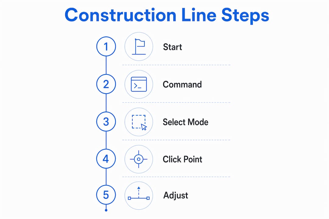
The XLINE command is AutoCAD’s dedicated tool for infinite construction lines. Type XLINE or XL in the command line and press Enter. AutoCAD then prompts you to choose a mode. There are five primary modes, each suited to a different drafting scenario.
Horizontal: Creates a line running the full width of the drawing space. Use this to lock in floor levels or datum references across an entire plan.
Vertical: Creates a line running the full height. Use this to establish column grid lines before placing any walls.
Angle: Prompts for a specific angle. Use this for raked ceilings, sloped roofs, or any geometry that deviates from orthogonal.
Bisect: Draws a line that bisects the angle between two existing lines. Use this when dividing a room diagonally or finding the center of an irregular space.
Offset: Creates a parallel construction line at a set distance from an existing line. Use this to mark setback distances, wall thicknesses, or structural offsets.
A typical architectural workflow using XLINE looks like this. Start a new floor plan. Type XL, select Vertical, and click along the X axis to place column grid lines at your structural spacing. Switch to Horizontal and place datum lines at each floor level. Use Offset to mark wall thicknesses on either side of each grid line. At this point, your entire structural layout exists as construction lines. You have not drawn a single permanent object line yet.
Pro Tip: Assign a keyboard shortcut to the XLINE command in your AutoCAD profile. Drafters who keep both hands on the keyboard move through layout phases significantly faster than those who reach for the mouse to access toolbar commands.
For complex projects, plugins with 23 or more commands extend XLINE’s capabilities to include parametric parallel lines, isometric construction grids, and batch offset creation. These tools become valuable when a project has dozens of grid lines that need to shift simultaneously during design development.
What are the best practices for managing construction lines in AutoCAD?
Layer management is the single most important practice for keeping construction lines under control. Every construction line belongs on a dedicated layer, named something clear like CONSTRUCTION or _GUIDE. That layer gets two critical settings: color set to gray or another low-contrast value, and plot style set to non-plot.
The non-plot setting is the key. It means the layer never prints, regardless of what else is visible on screen. You can leave every construction line in place and still produce a clean plotted drawing. That removes the pressure to delete construction lines before printing, which is where most drafting mistakes happen.
Create a CONSTRUCTION layer before starting any new drawing.
Set the layer color to gray (color index 8 or 9 works well in most plot styles).
Set the plot style to non-plot or assign a CTB/STB pen with zero width.
Toggle the layer off when checking the drawing’s visual clarity.
Freeze the layer before final plotting to confirm nothing bleeds through.
The light-to-dark workflow is the professional standard for architectural drafting. You start by blocking out the entire plan with construction lines, then trace over them with permanent object lines. This approach reduces rework by over 50% compared to drawing final lines from the start. The reason is simple: moving a construction line costs nothing. Moving a wall that has doors, windows, and dimensions attached to it costs significant time.
Pro Tip: Use the LAYWALK command to isolate your CONSTRUCTION layer and audit all guide lines before switching to object line work. This takes thirty seconds and catches misplaced lines before they become embedded in your final geometry.
Bulk deletion is straightforward when construction lines live on their own layer. Select all objects on the CONSTRUCTION layer using a layer filter, then delete. No hunting through the drawing for stray infinite lines. No risk of accidentally deleting a wall or annotation.
What are the common pitfalls when using AutoCAD construction lines?
The most damaging mistake is placing construction lines on the same layer as object lines. Once that happens, removing construction lines before printing becomes a manual, error-prone process. Drafters end up deleting lines one by one, and inevitably remove something they needed.
The second common mistake is treating XLINE as a permanent drawing tool. Some students draw construction lines and then simply leave them, assuming the thin weight makes them invisible. On screen, that may look acceptable. In a plotted drawing sent to a contractor or consultant, stray infinite lines create serious confusion about what is a building element and what is a guide.
“Professional drafting involves clear line hierarchy and removal of construction lines before final printing. Drawings that skip this step communicate ambiguity, not design intent.” — Drafting best practice standard
A third pitfall involves angle mode. Drafters sometimes use the Angle option without confirming the reference direction. AutoCAD measures angles from the positive X axis by default. If your drawing is rotated or uses a custom coordinate system, an angle of 45 degrees may not produce what you expect. Always confirm your User Coordinate System (UCS) before placing angled construction lines.
Advanced users working on large projects benefit from batch commands and dedicated plugins to create and manage multiple parallel or perpendicular construction lines at once. Manually placing thirty column grid lines one at a time is slow and introduces spacing errors. A plugin that accepts a spacing value and a count places all thirty lines in a single operation.
The difference between construction lines and guidelines also trips up students new to AutoCAD. Guidelines in some contexts refer to RAY objects, which extend infinitely in one direction only. XLINEs extend infinitely in both directions. Both serve as layout aids, but XLINEs are more common in architectural practice because they span the full drawing area without requiring a defined start point.
Key takeaways
The AutoCAD XLINE command creates infinitely extending, non-printing construction lines that form the structural scaffold of every professional architectural drawing before a single object line is placed.
Point | Details |
XLINE is the core command | Type XL to access five modes: Horizontal, Vertical, Angle, Bisect, and Offset. |
Line weight standards matter | Construction lines run 0.13–0.25 mm; object lines run 0.5–0.7 mm per ASME Y14.2. |
Layer discipline prevents errors | Place all construction lines on a non-plot CONSTRUCTION layer for clean plotting. |
Light-to-dark workflow cuts rework | Blocking out plans with construction lines first reduces rework by over 50%. |
Plugins extend XLINE capability | Tools with 23 or more commands handle parametric grids and batch parallel lines. |
Why construction lines changed how I teach AutoCAD
I spent years watching architecture students skip the construction line phase and go straight to drawing walls. The drawings looked fine on screen for the first hour. Then the client changed a room dimension, and the student had to manually adjust every connected element. That is not a workflow problem. That is a fundamentals problem.
The light-to-dark drafting method is one of the oldest principles in technical drawing, and it translates directly to AutoCAD. When students commit to blocking out their entire plan with XLINE before touching object lines, something shifts. They stop thinking about individual lines and start thinking about the whole layout. That mental shift produces better drawings faster.
The students who resist this workflow always give the same reason: it feels slower at the start. They are right. Placing construction lines before drawing walls adds ten minutes to the beginning of a project. What they do not see yet is that it removes two hours of corrections at the end. I have seen this play out on student projects and on professional jobs. The math always works out the same way.
My honest advice: treat the CONSTRUCTION layer as non-negotiable from your very first AutoCAD drawing. Build the habit before you build the drawing. The AutoCAD drawing standards that govern professional practice are built on exactly this kind of line discipline. The sooner you internalize it, the faster you will produce work that looks and behaves like a professional drawing.
CAD tools will keep evolving. BIM workflows will keep changing what architects do on screen. But the principle of establishing layout before committing to final geometry is not going away. Construction lines are the expression of that principle in AutoCAD, and they are worth mastering completely.
— Steve
Build your AutoCAD skills with S15studio
Mastering construction lines is one piece of a much larger AutoCAD skillset that architecture students and design professionals need to work at a professional level. S15studio, founded by Autodesk Certified Trainer Steve Fagan, offers project-based training that covers everything from fundamental AutoCAD techniques to advanced BIM workflows in Revit.

The courses at S15studio are built around real architectural scenarios, not abstract exercises. You practice the exact workflows that appear on live projects, including layer management, line hierarchy, and the XLINE methods covered in this article. Whether you are preparing for Autodesk certification or building your drafting speed from scratch, the complete AutoCAD and Revit training at S15studio gives you a structured path from beginner to professional-grade output.
FAQ
What is a construction line in AutoCAD?
A construction line in AutoCAD is an infinitely extending, non-printing guide line created with the XLINE command. It is used to establish alignment, proportion, and layout before permanent object lines are drawn.
How do you draw construction lines in AutoCAD?
Type XL in the command line and press Enter, then choose a mode: Horizontal, Vertical, Angle, Bisect, or Offset. Click to place the line across your drawing canvas.
What is the difference between construction lines and object lines?
Construction lines are temporary, non-printing, and thin (0.13–0.25 mm). Object lines are permanent, printed, and thick (0.5–0.7 mm) per ASME Y14.2 standards.
Why should construction lines be on a separate layer?
Placing construction lines on a dedicated non-plot layer prevents them from appearing in printed drawings and allows batch deletion without affecting permanent geometry.
Do construction lines print in AutoCAD?
Construction lines do not print when their layer is set to non-plot. If placed on a standard plotting layer, they will print, which is one of the most common drafting mistakes to avoid.
Recommended
Comments