Revit Structural Framing Explained for Engineers
- Steve Fagan

- 1 day ago
- 8 min read

Revit structural framing is defined as the parametric modeling of load-bearing elements, including beams, columns, trusses, and slabs, within a Building Information Modeling environment. This process focuses on accurate documentation and coordination, not internal structural calculations. Those calculations require external structural analysis software. Understanding Revit structural framing means understanding how parametric families, beam systems, and placement workflows combine to produce a coordinated, construction-ready model. This article covers the core tools, concepts, and best practices that architecture and engineering professionals need to work confidently with structural framing in Revit.
What are the main types of structural framing elements in Revit?
Revit structural framing focuses on modeling and documentation, explicitly excluding design calculations and code compliance. That distinction matters. You are building a representation of the structure, not running load analysis. The framing model feeds coordination, scheduling, and construction documentation workflows.
The four core element categories you work with are:
Beams: Horizontal members that span between supports. Beams carry floor and roof loads to columns or walls. In Revit, beam families are parametric, meaning you control section size, material, and length through type and instance parameters.
Columns: Vertical members that transfer loads from beams and slabs down to foundations. Structural columns in Revit behave differently from architectural columns. They attach to levels and respond to structural connections.
Trusses: Assemblies of members that span long distances. Revit truss families define the chord and web geometry parametrically, so changing the span updates the entire assembly.
Slabs (Structural Floors): Horizontal plate elements that carry live and dead loads. Structural floors in Revit carry span direction data and can host reinforcement elements.
Each of these families is parametric. That means geometry, material, and behavior are driven by parameters rather than fixed shapes. When an architectural change occurs, updating a parameter propagates through the model automatically. This is the core advantage of BIM coordination over traditional drafting. Beams span horizontally between columns, columns transfer loads vertically, and slabs tie the system together at each level. Understanding how these elements relate to each other is the foundation of effective structural modeling in Revit.
How does the Beam System tool work for efficient structural framing?

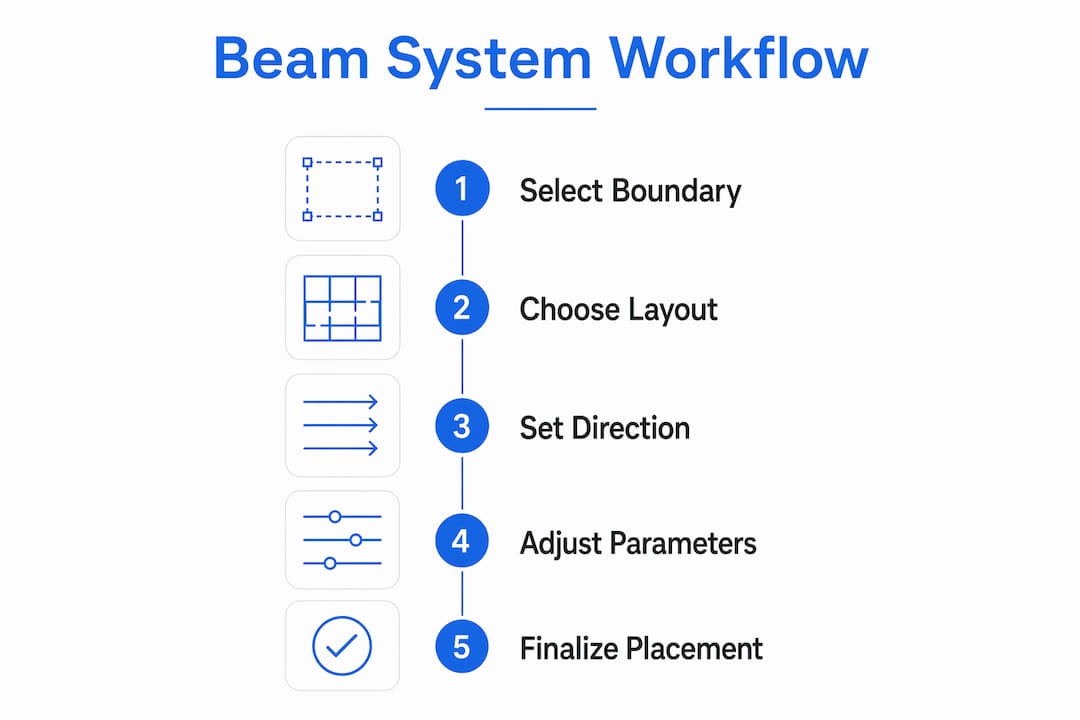
The Beam System tool is Revit’s primary method for rapidly placing arrays of framing members across a floor or roof boundary. Instead of placing individual beams one by one, you sketch a closed boundary and define layout rules. Revit generates the full array automatically.
The key layout rules available in the Beam System tool are:
Fixed Distance: Sets an exact spacing between beam centerlines. Use this when engineering drawings specify a precise joist spacing, such as 400mm or 600mm on center.
Maximum Spacing: Revit places as many beams as possible without exceeding the defined maximum. This is useful when the exact count is flexible but the spacing limit is fixed.
Fixed Number: Places a set number of beams regardless of the boundary size. Revit calculates the spacing automatically.
Clear Distance: Controls the gap between beam faces rather than centerlines. Use this when clearance between members matters more than centerline spacing.
The Beam System tool also includes a Direction Line option. This line controls where the first beam in the array lands. Without it, Revit places the first beam at a default offset from the boundary edge, which often misaligns with columns or grids. Using the Direction Line in the sketch editor, rather than nudging beams manually after placement, gives you exact control over initial beam position.
Pro Tip: Always use the Direction Line option when your beam system must align with a column grid. Draw the direction line directly over the grid line where the first beam should land. This eliminates the manual adjustment step and keeps your model clean.
A common frustration with beam systems is the default top justification applied to structural framing families. Revit hardcodes beams in a beam system to justify from the top of the section. If your family geometry is not set up to match this, beams appear at the wrong elevation. The fix is to adjust the family geometry itself and apply a global Z-offset to correct the bearing condition. Trying to fix this with manual overrides in the project creates inconsistencies that compound over time.
What are parametric families and shared parameters in Revit structural framing?
Parametric families are the engine behind every structural element in Revit. A family defines the geometry, behavior, and data of an element. Parameters control that family, and there are two types you need to understand.
Instance parameters apply to a single placed element. Changing an instance parameter on one beam does not affect other beams of the same type. Use instance parameters for values that vary per element, such as a custom Z-offset or a specific mark number.
Type parameters apply to every element of that family type. Changing a type parameter updates all placed instances simultaneously. Section size and material are classic type parameters. If you change a W12x26 to a W14x30, every beam of that type updates across the entire model.
Shared parameters go further. They allow the same parameter to appear in both the family and a project schedule, and across multiple families. When a shared parameter changes in the family, it updates on every sheet and schedule that references it automatically.
A practical example is the parametric roof truss family. A well-built truss family uses instance parameters for span and rise, and type parameters for standardized pitch variants. When the architect changes the roof pitch, updating the slope parameter in the truss family propagates the change across every truss in the model and every sheet that shows truss data. No manual redrawing required.
Pro Tip: Use shared parameters for any data that needs to appear in a schedule or tag. If you use a regular family parameter instead, you cannot add it to a project schedule without rebuilding the family. Set up shared parameters at the start of a project, not after families are already placed.
Parametric truss families that combine instance and type parameters correctly give you flexibility without geometry duplication. You build one family and scale it across projects with different roof pitches. That is the difference between a family that saves time and one that creates rework.
What best practices improve accuracy in placing and modifying structural framing?
Accurate structural framing placement depends on a clear workflow for controlling which elements move and which elements stay fixed. The drivers vs. dependents model is the most reliable approach.
Pin your drivers early. Grids and reference planes are drivers. They define the structural intent of the model. Pin these elements as soon as they are confirmed. A pinned grid cannot be accidentally moved, which prevents the cascade of warnings and misalignments that follow grid shifts.
Leave dependents unlocked until milestones. Beams, columns, and slabs are dependents. They should remain unpinned during active design so they can respond to changes. Pin them only at major project milestones when the structural layout is frozen.
Use Align before Pin. The Align tool locks an element’s face or centerline to a reference. After aligning a beam to a grid, pin the beam to preserve that relationship. If you pin without aligning first, the beam is locked in the wrong position.
“Pinning drivers and leaving dependents unlocked preserves structural intent and reduces model warnings during project evolution.” — Revit structural modeling best practice
Setting structural usage for each beam is a step many students skip, and it causes problems downstream. Revit allows you to label a beam as a girder, joist, purlin, or other usage type. This label affects how Revit handles connections and how the element appears in structural documentation. A beam labeled as a girder connects differently than one labeled as a joist. Getting this right at placement saves significant rework when the structural engineer reviews the model.
Adjusting family geometry and justification is another area where precision pays off. When a beam appears at the wrong elevation inside a beam system, the instinct is to apply a manual Z-offset in the project. That works for one beam. It fails when you have 40 beams in the system and the floor level changes. The correct fix is to adjust the family geometry so the insertion point matches the expected justification, then apply a single global offset if needed. One fix in the family corrects every instance in the project.
Key takeaways
Revit structural framing is the parametric modeling of load-bearing elements within BIM, requiring mastery of families, beam systems, and placement workflows to produce accurate, coordinated documentation.
Point | Details |
Framing vs. analysis | Revit models and documents structural elements; it does not perform load calculations or code compliance checks. |
Beam System layout rules | Use Fixed Distance, Maximum Spacing, or Clear Distance rules to control joist arrays without placing beams individually. |
Direction Line precision | Always use the Direction Line in beam system sketches to control first-beam placement and align with column grids. |
Instance vs. type parameters | Use instance parameters for per-element variation and type parameters for section sizes that update all placed instances at once. |
Drivers vs. dependents | Pin grids early and leave framing elements unlocked until design milestones to prevent coordination drift and model warnings. |
What I’ve learned from teaching Revit structural framing
Most students come to structural framing expecting it to work like a drafting task. Place the beam, move on. The moment they hit a beam system justification issue or a parameter that won’t schedule, the model starts to feel like it’s fighting them. That frustration is a signal. It means the underlying parametric logic hasn’t clicked yet.
The single biggest shift I’ve seen in students who go from struggling to confident is this: they stop treating Revit as a drawing tool and start treating it as a database with geometry attached. Every parameter is a data field. Every family is a record. When you think that way, the rules around shared parameters, type vs. instance, and drivers vs. dependents stop feeling arbitrary and start making sense.
My practical advice is to work closely with the structural engineer from day one. Get their grid layout and level data before you place a single beam. Structural framing built on a confirmed grid is a model you can update. Structural framing built on assumptions is a model you rebuild. Also, resist the urge to build custom geometry for every unique condition. Standard families with well-set parameters handle more situations than most people expect. Save custom geometry for the cases where standard families genuinely cannot do the job. If you’re getting started with Revit or working to sharpen your structural modeling skills, building that parametric mindset early is the fastest path to producing work that holds up under coordination review.
— Steve
S15studio’s Revit training for structural framing skills
Structural framing in Revit rewards structured learning. Picking up individual tips from forums works for isolated problems, but it leaves gaps in the foundational knowledge that cause bigger problems later.
S15studio, founded by Autodesk Certified Trainer Steve Fagan, offers project-based Revit training built for architecture and engineering professionals at every level. The Complete Revit and AutoCAD Training course covers structural modeling workflows, parametric family creation, beam system placement, and coordination best practices in a structured sequence. You build real skills on real project scenarios, not isolated exercises. Whether you are preparing for Autodesk certification or working to close specific skill gaps, the training is built around the workflows you actually use on the job.
FAQ
What is structural framing in Revit?
Structural framing in Revit is the parametric modeling of load-bearing elements such as beams, columns, trusses, and slabs within a BIM environment. It focuses on documentation and coordination, not structural calculations.
How does the Beam System tool place framing members?
The Beam System tool uses a sketch boundary and layout rules like Fixed Distance or Maximum Spacing to automatically generate arrays of beams or joists across a defined area.
What is the difference between instance and type parameters in Revit families?
Instance parameters apply to a single element and can vary per placement. Type parameters apply to every element of that family type and update all instances simultaneously when changed.
Why do beams appear at the wrong elevation in a beam system?
Revit structural framing families default to top justification in beam systems. The correct fix is to adjust the family geometry and apply a global Z-offset rather than manually overriding individual beam elevations in the project.
What does structural usage mean for a beam in Revit?
Structural usage labels a beam as a girder, joist, purlin, or other type, which affects how Revit handles structural connections and how the element is represented in documentation and coordination workflows.
Recommended
Comments