
AutoCAD Map Integration Explained for GIS Professionals
- Steve Fagan

- Jul 26
- 8 min read

What is AutoCAD Map 3D integration and how does it work?
AutoCAD Map 3D integration connects external spatial data sources directly into the AutoCAD environment using native APIs and open standards. Instead of importing a static image and hoping it lines up, you get a live, editable link to GIS databases, web map services, and geospatial APIs. The drawing updates when the source data changes.
The core mechanism relies on two standards:
FDO (Feature Data Objects): Autodesk’s native data access technology that reads and writes directly to spatial databases like Oracle, PostgreSQL, and SQL Server without file conversion.
WMS (Web Map Service): An OGC-standard protocol that streams raster map imagery from remote servers into your drawing as a dynamic background layer.
Spatial databases: Oracle Spatial, PostGIS, and SQL Server Spatial are all accessible natively through FDO connections.
Web-based map services: Google Maps (via third-party tools), Nearmap WMS, and government tile services all connect through the Data Connect workflow.
For infrastructure planning, this matters because your utility corridors, parcel boundaries, and topographic data stay synchronized with authoritative sources. You are not redrawing from a PDF printout.
Table of Contents
How AutoCAD Map 3D APIs enable map integration
The AutoCAD Map 3D toolset exposes several layers of API access, each serving a different integration purpose.

FDO API is the foundation. It provides direct editing of geospatial data stored in geodatabases without requiring an intermediate export step. You connect, query, and edit features in place. Supported providers include Oracle, PostgreSQL, SQL Server, SHP files, and SDF.
Geospatial Platform API (.NET) lets developers build custom map-rendering workflows. The BuildMap sample in the AutoCAD Map 3D SDK demonstrates how to load data programmatically and render it to model space, which is the starting point for custom WMS rendering through code.
MapImport / MapExport tools: These preserve coordinate systems and spatial metadata during data transfer. Using standard AutoCAD Import instead of MapImport loses spatial references and attribute data.
Display Manager: The visual interface for managing data connections, layer order, and symbology for all connected spatial sources.
Data Connect panel: The UI entry point for adding FDO, WMS, and SDF connections without writing code.
For developers, the .NET platform API accessed through Visual Studio is the recommended path for custom WMS rendering or automated data workflows.
How to integrate Google Maps into AutoCAD using Spatial Manager
Google Maps does not offer a native WMS endpoint for AutoCAD. The practical solution is Spatial Manager, a third-party plugin that bridges Google’s tile services into the AutoCAD environment as a georeferenced background layer.
Assign a coordinate system to your drawing. Open the Map 3D workspace, type _MAPCSASSIGN, and set your drawing CRS to match your project (typically a UTM zone or State Plane system). Without this step, the Google Maps imagery will not align with your CAD geometry.
Install Spatial Manager for AutoCAD. Download and install the plugin from the Spatial Manager website. It integrates directly into the AutoCAD ribbon.
Open the Background Map panel. In the Spatial Manager ribbon tab, select “Background Maps” and choose Google Maps (or Google Satellite) from the provider list.
Set the map scale and view. Zoom to your project area. Spatial Manager fetches tiles dynamically at the current view scale, so the imagery sharpens as you zoom in.
Adjust transparency and layer placement. Place the background map on a dedicated layer (e.g., BGMAP-GOOGLE). Set transparency to 40–60% so your CAD linework remains readable over the imagery.
Save and export. Use MapExport to write the combined drawing with embedded geospatial metadata. For sharing, export as GeoTIFF or PDF with geospatial extensions enabled.
Pro Tip: Lock the background map layer before sharing the DWG file. This prevents collaborators from accidentally moving the imagery and breaking the georeferenced alignment.
Using WMS services for dynamic map imagery in AutoCAD Map 3D
WMS is the standard for streaming raster map imagery from authoritative sources: Nearmap, USGS, state GIS portals, and municipal mapping agencies all publish WMS endpoints. Here is how the workflow runs.
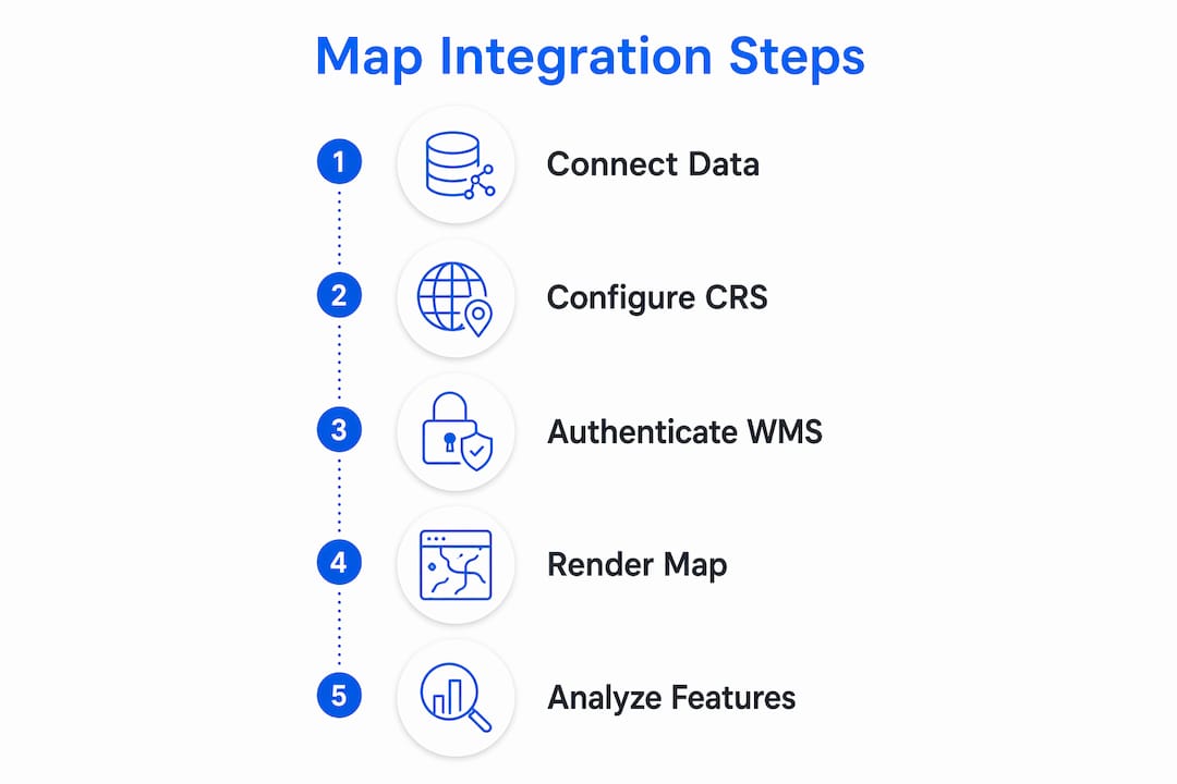
Understanding WMS in this context: WMS delivers georeferenced raster tiles on demand. Unlike a static image attach, the server renders the image at the requested extent and resolution each time you pan or zoom.
Steps to connect:
In the Map 3D workspace, open Display Manager and click Data > Connect to Data.
In the Data Connect window, select Add WMS Connection.
Enter the server URL and a connection name. If the service requires authentication, enter credentials here.
Click Connect. The dialog lists all available layers from that WMS server.
Select the layers you need (orthoimagery, contours, parcels) and confirm.
Match the coordinate system to your drawing CRS before clicking Add to Map.
Managing image layers:
Place WMS imagery on a dedicated layer and use the IMAGEFRAME system variable to control whether the image border is selectable and visible.
Adjust transparency in layer properties to balance imagery visibility against CAD linework.
Freeze the WMS layer when plotting to avoid slow render times if the service is not needed in output.
Troubleshooting common issues:
Spatial mismatch: Almost always a coordinate system problem. Run _MAPCSASSIGN and confirm the drawing CRS matches the WMS service’s native projection.
Connection failure: The default WMS version is 1.3.0, but some servers require 1.1.1. Edit the connection and try alternate versions.
Corporate proxy blocks: Configure proxy address, port, and credentials in the connection dialog. Many enterprise networks block outbound WMS requests by default.
AutoCAD vs. AutoCAD Map 3D vs. Civil 3D: which tool do you need?
These three products share a common DWG foundation but serve distinct professional roles. Choosing the wrong one costs time and money.
AutoCAD: General-purpose 2D drafting. No GIS awareness, no spatial database connections, no coordinate system management. Right for documentation, details, and cross-discipline drawing sets.
AutoCAD Map 3D: GIS-focused toolset built on AutoCAD. Adds FDO data connections, WMS integration, topology tools, and spatial analysis. The right choice when your work involves managing or consuming geographic data for planning, utilities, or land use.
Civil 3D: Built on AutoCAD and includes the Map 3D toolset. Adds dynamic alignments, corridors, surfaces, pipe networks, and grading. Civil 3D subscriptions include Map 3D, but Map 3D subscriptions do not include Civil 3D.
Map 3D acts as Autodesk’s GIS engine: it integrates spatial data to inform design. Civil 3D consumes that spatial data for dynamic civil project modeling. A GIS analyst managing utility networks belongs in Map 3D. A civil engineer designing a road corridor belongs in Civil 3D.
Authentication methods for WMS connections
WMS services use several authentication schemes, and knowing which one a server requires saves significant troubleshooting time.
No authentication (public services): Many government WMS endpoints (USGS, state GIS portals) are open. You enter the URL and connect without credentials.
Basic HTTP authentication: The most common method for commercial services like Nearmap. The Data Connect dialog in AutoCAD Map 3D has username and password fields. Enter them before clicking Connect.
Token-based authentication: Some services pass an API key as a URL parameter rather than through a login dialog. Append the key directly to the WMS URL: https://service.example.com/wms?apikey=YOUR_KEY&.
IP whitelisting: Enterprise and government WMS servers sometimes restrict access by IP address rather than credentials. If your connection fails with no obvious error, contact the service provider to confirm your network’s outbound IP is whitelisted.
For corporate environments, proxy configuration is a separate layer on top of authentication. Set the proxy address and port in the WMS connection dialog, and include proxy credentials if your network requires them.
How to handle coordinate systems during map integration
Coordinate system mismatches are the single most common cause of integration failures. The fix is always the same: assign the correct CRS before you connect to any external data source.
Run _MAPCSASSIGN at the command line and select the coordinate system that matches your project. For US infrastructure work, this is typically a State Plane zone (NAD83) or a UTM zone. If no coordinate system is assigned, the WMS default projection often causes features to appear hundreds of miles from their actual location.
When connecting FDO data sources, AutoCAD Map 3D reads the source CRS and reprojects on the fly to match the drawing. This works well for small areas but can introduce distortion over large extents. For statewide or national datasets, consider working in a geographic coordinate system and projecting only for output.
Pro Tip: Store the project CRS in a drawing template (.DWT) so every new file in the project starts with the correct coordinate system already assigned.
Best practices for map data performance in AutoCAD Map 3D
Large WMS connections and FDO datasets slow drawings down fast. These practices keep things responsive.
Limit the active query extent. FDO connections load features within the current view by default, but you can define a spatial filter to restrict the query to your project boundary. This cuts load times dramatically on large utility datasets.
Use dedicated layers for map imagery. Place every WMS or background map on its own layer. Freeze those layers when you do not need them. The IMAGEFRAME variable controls whether image borders are selectable, which prevents accidental moves.
Cache WMS tiles locally where possible. Some WMS clients support tile caching. If your workflow involves repeated access to the same area, a cached tile set eliminates repeated server requests.
Use MapImport and MapExport rather than standard AutoCAD import commands. These tools preserve coordinate systems and spatial metadata, which matters when the file moves between team members or into other GIS platforms.
Using feature data alongside map imagery for analysis
The real power of AutoCAD Map 3D integration is not the background imagery. It is the ability to run spatial analysis on live feature data while the map provides geographic context.
Connect an FDO source (a PostGIS utility network, for example) and the features appear as editable CAD objects with their database attributes intact. You can query by attribute (“show all pipes installed before 1980”), run buffer analyses, and generate reports, all while the WMS orthoimagery sits underneath as a reference.
For infrastructure planning, a typical workflow combines a Nearmap WMS layer for current aerial imagery, a parcel FDO connection from the county GIS, and a utility network from an enterprise geodatabase. The planner works in one drawing, with live data from three authoritative sources, and exports a georeferenced PDF for stakeholder review using MapExport.
This is what separates Map 3D from plain AutoCAD: the drawing is not just a picture of the data. It is connected to it. For professionals ready to go deeper on these workflows, S15studio’s AutoCAD mastery course covers Map 3D spatial integration alongside the full AutoCAD toolset in a structured, project-based format.

Key Takeaways
AutoCAD Map 3D integration connects live spatial data sources directly into the CAD environment through FDO and WMS standards, replacing static image imports with editable, georeferenced data.
Point | Details |
Assign CRS first | Run _MAPCSASSIGN before any WMS or FDO connection to prevent spatial mismatches. |
FDO enables live editing | Feature Data Objects connect directly to Oracle, PostgreSQL, and SQL Server without file conversion. |
WMS version matters | Default is 1.3.0; switch to 1.1.1 if a server connection fails. |
Use MapImport/MapExport | These tools preserve coordinate systems and metadata that standard AutoCAD import commands drop. |
Layer discipline is critical | Place all map imagery on dedicated layers and use IMAGEFRAME to control visibility and selection. |
Recommended
Comments