
AutoCAD Offset Command: Distance, Through and Multiple


The OFFSET command draws a copy of a line, arc, circle or polyline at a set distance from the original, so the copy runs parallel to it. Type O, press Enter, type a distance, pick the object, then click the side you want the copy on. That is the whole routine. Most of the speed and most of the problems come from the options around it: Through, Multiple, Erase, Layer, and a few system variables that quietly change what the command does.
This guide covers each of them in the order you meet them at the keyboard, with the fixes for the usual faults. It is written for architects, technicians and students who draw walls, grids and setting-out lines in AutoCAD every day.
TL;DR
OFFSET creates parallel lines, concentric circles and parallel curves. The shortcut is O, as Autodesk’s shortcut guide lists it.
Use Distance when you know the gap (a 100 mm cavity, a 215 mm wall). Use Through when the new line must land on a specific point.
The command repeats on its own until you press Enter. Multiple repeats the offset from the last copy at the same distance.
The wrong distance usually means a retained Through value or Dynamic Input switched off. Press F12 first.
Offset objects land on the source object’s layer unless you change the Layer option.
Table of Contents
What OFFSET does and when to use it
According to Autodesk’s 2026 help for OFFSET, the command creates concentric circles, parallel lines and parallel curves. You can offset at a specified distance or through a point, then trim and extend the results. Autodesk describes this as an efficient way to build drawings that contain many parallel lines and curves.
In architectural work that covers a lot of ground:
Wall thickness: draw one wall centreline or face, offset it by the thickness, and you have both faces.
Grids and setting-out: offset a base line repeatedly to place column lines at regular bays.
Cavities and finishes: offset an external wall outline inwards for insulation, block, plasterboard and render build-ups.
Curved geometry: offset an arc or circle and you get a concentric one, larger or smaller depending on the side you click.
Site and boundary offsets: set a building line back from a boundary polyline by a fixed distance.
The reason OFFSET beats copying and moving is precision. A copy with a typed displacement moves in a straight direction. OFFSET measures perpendicular to the object, so it follows an arc, a spline or a polyline with a dozen segments without you working out any geometry.
The basic routine: offset by a distance
The ribbon path is Home tab, Modify panel, Offset, per Autodesk’s step-by-step page. Faster is the keyboard:
Type O and press Enter (or Space).
At the distance prompt, type the value, for example 215, and press Enter. You can also click two points in the drawing to set the distance by measurement.
Select the object to offset. You must click it directly; you cannot window-select for OFFSET.
Click on the side where the copy should appear. Only the side matters, not how far you move the cursor.
The command asks for another object. Select it, or press Enter to finish.
Two habits save time. First, keep the drawing units in mind: if your drawing is in millimetres, typing 215 gives 215 mm. Second, keep your hand on the Enter key. Because the command loops, you can offset a whole series of objects without retyping the distance.
A worked example: a 215 mm wall from a single line
You have a 6000 mm line representing the internal face of a wall. Type O, enter 215, pick the line, and click above it. A second line appears 215 mm away, 6000 mm long. Press Enter. You now have both faces of the wall. If the wall turns a corner, the offset of a polyline carries around the corner in one go, which is why architects usually draw wall outlines as polylines rather than loose lines.
Offset through a point
Sometimes you do not know the distance; you know where the new line has to pass. Start OFFSET and enter T for Through. Select the object, then click the point it must pass through. An endpoint, intersection or midpoint with object snaps on gives exact placement.
Autodesk’s help adds a practical tip for polylines with corners: specify the through point near the midpoint of a segment, not near a corner. Near a corner the program has to decide which segment you mean, and the result is not what you expect.
Typical uses include drawing a line parallel to a sloping roof edge that passes through a ridge point, or dropping a datum line through an existing column centre.
Offsetting several times: continuous and multiple offsets
There are two different ideas here, and the difference matters.
Repeating the command. Autodesk’s help explains that OFFSET prompts again for the next object after each offset, and you press Enter to exit. This is the default. Offset a wall line, then immediately select a different line and offset it by the same distance.
The Multiple option. Enter M at the “select object” prompt. In Multiple mode the command repeats the offset using the current distance. Each side click creates another copy, so you can build a set of parallel lines from one source with only clicks. This is the quickest way to lay out a series of equally spaced lines for a window mullion pattern, floor boards or a set of column grids. Autodesk’s help notes that Undo reverses the previous offset, so a mis-click costs one keystroke, not a restart.

A practical note: Multiple measures from the original object each time, so ten clicks at a 100 mm distance produce lines at 100, 200, 300 mm and so on from the source, in the direction of each click. For more regular layouts, such as many identical copies in a grid, the AutoCAD Array command is the better tool, and it handles rectangular, polar and path patterns.
Erase, Layer and the other options
After you press O, the prompt shows several keywords. The ones worth knowing:
Option | Key | What it does |
Through | T | Offsets so the new object passes through a point you pick |
Erase | E | Deletes the source object after the offset, so you effectively move it by a distance |
Layer | L | Chooses whether new objects go on the current layer or the source layer |
Multiple | M | Repeats the offset at the current distance |
Undo | U | Reverses the last offset |
Exit | Enter | Ends the command |
The Erase and Layer options are described in Autodesk’s OFFSET reference. Erase is useful when the original was only a construction line. Layer is the one that surprises people.
Why your offset lands on the wrong layer
By default an offset object sits on the same layer as its source, whichever layer is current, as this university drafting chapter points out. If you offset a centreline to make a wall face, the wall face arrives on the centreline layer, with the centreline’s linetype and colour.
You have two ways to deal with it. Set the Layer option to Current before you offset, so the new objects take the layer you have active. Or offset first and then change the layer in the Properties palette or with Match Properties. If your layer structure is well organized, a quick layer change is routine; the AutoCAD layer standards guide shows how to set up names and properties so the right layer is always one click away. When you want to flip between layer views while you work, the layer states workflow restores them in seconds.
Offsetting polylines, circles and arcs
The object type changes what you get:
Circles and arcs: the copy is concentric. Click outside for a larger one, inside for a smaller one, as Autodesk’s AutoCAD Web help describes.
Closed polylines: every segment offsets together and the result stays closed. Because the distance is measured perpendicular to each segment, corners are recalculated, not simply shifted.
Open polylines: the segments in the middle become longer or shorter, while the first and last segments stay parallel to the originals.
Loose lines: each line offsets alone, leaving gaps or overlaps at corners that you then clean up with FILLET, or with trim and extend.
That last point is why drawing outlines as polylines pays off. If you do end up with overshoots or gaps, the trim and extend explainer walks through cleaning them up quickly.
Controlling the corners with OFFSETGAPTYPE
When you offset a polyline outwards, the corners can be left with gaps. The system variable OFFSETGAPTYPE controls how those gaps close. Autodesk’s Tuesday Tips post explains that 0 gives the normal offset, and 1 fillets the segments, using an arc radius equal to the offset distance. A chamfer setting also exists, but the post notes the chamfer is accurate only at the point perpendicular to the corner, so use the fillet setting if you need a uniform distance all the way round. The value is stored in the registry and applies to all drawings until you change it.
For a rounded kerb line or a rounded plate edge, set it to 1 and the outward offset will have rounded corners that keep a true distance from the original.

Fixing OFFSET when it does not work
The most common search behind this topic is some version of “why isn’t offset working?” Run through these in order.
The copy appears at the wrong distance
Autodesk Support describes two causes: the Through value is being retained instead of your newly typed value, or Dynamic Input is turned off. Press F12 to switch Dynamic Input on, or reset AutoCAD to its defaults.
The same Autodesk Tuesday Tips post explains the mechanism behind the first cause. The OFFSETDIST variable stores the last distance and sets the mode: a negative value such as -1.00 means Through, and a positive value means Distance. If the command opens in Through mode when you expected a distance, type a positive distance at the prompt.
“Requires numeric distance, two points, or option keyword”
This error appears when the drawing units are set to Decimal but you typed the value in architectural or engineering style, such as feet and inches. Autodesk’s support article gives the fix: type UNITS and set the type to Architectural or Engineering. Those settings display feet and inches and assume each drawing unit is one inch. In Ireland most drawings are metric, so the more likely cause is a stray character, a comma where a decimal point belongs, or text typed into the wrong prompt. Re-enter the number as plain digits.
Nothing happens when you click the object
Check these:
You clicked a spot that is not on the object. OFFSET needs a direct pick.
The object is on a locked layer. Unlock it first.
The object is a block, a hatch or a text object. OFFSET works on lines, arcs, circles, ellipses, splines and polylines, not on those types. Explode a block only if you have to, and only on a copy.
You are offsetting an xref. Xref geometry cannot be offset directly unless you work in the host file.
The offset side is ambiguous
On tight polyline geometry, a click near a corner can create something odd. Click the side well away from any vertex, or use Through with a point near the middle of a segment.
Speeding up OFFSET in daily drafting
A few habits make the command nearly automatic:
Learn O. One keystroke starts the command. It is among the most useful entries in a list of AutoCAD keyboard shortcuts worth memorizing.
Draw closed outlines as polylines. Use PLINE or the rectangle tool, or join loose lines with PEDIT, so one offset moves every edge.
Offset first, trim second. Offset generously, then trim and extend. It is faster than drawing each line to length.
Set the layer before you start. Decide whether the Layer option should be Current or Source, and stay consistent through the drawing.
Use Undo inside the command. Typing U removes only the last offset without leaving the command.
Check against your standards. Wall thicknesses, cavity widths and lineweights should follow your office’s conventions; the drawing standards overview is a good reference for what to keep consistent.
If you are setting up a new architectural drawing, the architectural drawing setup guide shows where OFFSET fits in the larger sequence of units, layers and templates.
Differences across AutoCAD versions
The command behaves the same in the full program and in LT. On the Mac, the 2025 AutoCAD LT for Mac help lists the same options (Offset Distance, Through, Erase and Layer, plus Exit, Multiple and Undo) and places the button on the Drafting tab, Modify panel, or under Modify, Offset. Windows users find it on the Home tab, Modify panel. The keyboard route, O, is identical.
Perspective
Offset looks like a beginner command, and that is why people stop learning it. In practice, a drafter who really knows OFFSET draws faster than one who knows twenty other commands badly. The pattern we teach is simple: draw one clean polyline, offset it for every build-up, set the layer deliberately, then trim. That sequence alone covers most plan and section work. When students send us drawings to review, the trouble is rarely OFFSET itself. It is the habits around it: loose lines instead of polylines, objects on the wrong layer, units that do not match the way the numbers are typed. Fix those and the command stops being a problem. That is how we build our AutoCAD training. You learn each command by drawing an actual project, so you meet OFFSET when you need a wall, not as an isolated exercise. As an Autodesk Certified Trainer, I want you to be quick and tidy at the board, because that is what an office notices. Steve
Learn OFFSET inside a real drawing set
Knowing the options is the easy part. Using them in the right order on a full floor plan, with layers, templates and standards, is where drafting speed comes from. Our AutoCAD Training course takes you from beginner to advanced with project-based lessons built around real-world workflows. It costs €79 as a one-off payment, and it includes direct trainer support, lifetime access to the materials and a completion certificate. It is backed by a money-back guarantee.
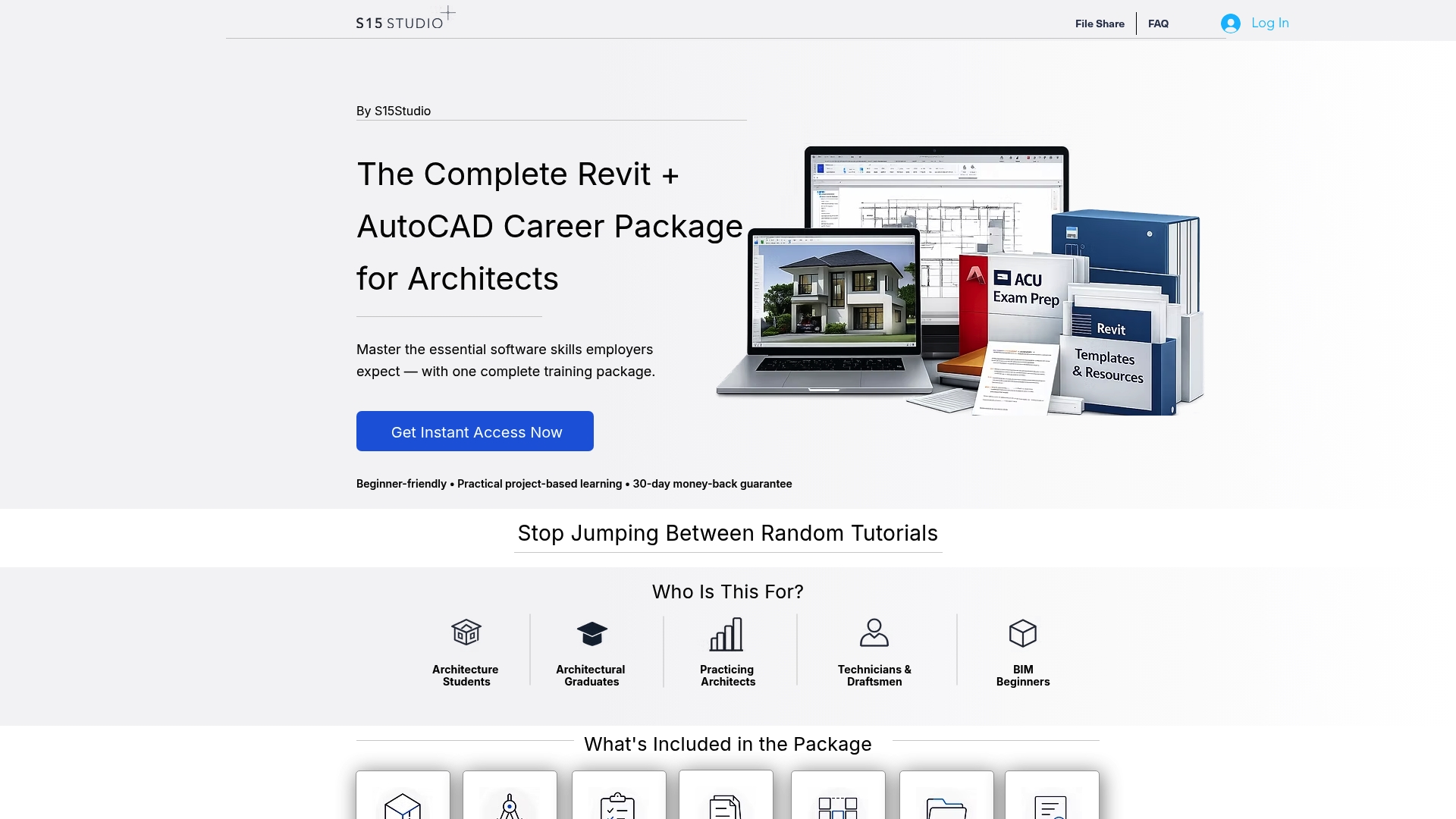
If you want the full path, the Complete Revit and AutoCAD training pairs both programs with exam practice for the Autodesk Certified User certification.
FAQ
What is the shortcut key for the offset command in AutoCAD?
The shortcut is O. Type it at the command line and press Enter or Space. Autodesk’s shortcut guide lists O for OFFSET. The ribbon alternative is Home tab, Modify panel, Offset.
How do I offset multiple times in AutoCAD?
The command repeats by default, so after each offset you can pick another object and press Enter when you are done. For several copies from one source at the same distance, enter M for Multiple and click once for each copy. Type U to undo the last one.
Can I offset an object through a specific point?
Yes. Start OFFSET, enter T for Through, select the object, then pick the point the new object must pass through. Use object snaps for accuracy, and on polylines pick a point near the middle of a segment, not near a corner.
Why does OFFSET give a different distance from the one I typed?
Usually a retained Through value or Dynamic Input being off. Press F12 to turn Dynamic Input on, and type a positive distance at the prompt. If the problem persists, reset AutoCAD to its defaults, as Autodesk Support advises.
Does the offset object go on the current layer?
Not by default. It stays on the source object’s layer. Use the Layer option (L) to choose Current if you want the copy on the layer you have active, or change the layer afterwards in the Properties palette.
Sources
Recommended
Comments