
AutoCAD PDF Import and Tracing: PDFIMPORT vs Attach-and-Trace
- Steve Fagan
- 11 hours ago
- 12 min read

Vector PDF from a CAD program? Run PDFIMPORT and you’ll have editable lines, polylines, arcs, and text in under a minute. Scanned drawing or raster PDF? Attach it as an underlay, scale it to a known reference dimension, and trace on a dedicated layer — or push it through Autodesk Raster Design if you have a stack of pages to process. Those two decisions cover nearly every situation you’ll face.
Here’s the quick decision tree before you go further:
Vector PDF (exported from CAD or BIM software): use PDFIMPORT via the Insert tab or the command line. AutoCAD recovers the real geometry directly as editable entities.
Raster PDF (scanned drawing, photographed plan, or low-quality export): attach with PDFATTACH, scale immediately using SCALE with the Reference option, then trace manually on a separate layer.
Large batch of scanned pages: consider Autodesk Raster Design for semi-automated vectorization, or test a third-party raster-to-vector converter on a sample page first.
Unsure which type you have? Zoom into the PDF in a viewer like Adobe Acrobat. If the lines stay crisp at 800%, it’s vector. If they pixelate, it’s raster.
Steve Fagan, Autodesk Certified Trainer and founder of S15studio, built the workflows below around real project practice. The goal is clean, scalable geometry on the first pass.
Table of Contents
How to convert a vector PDF to editable AutoCAD geometry with PDFIMPORT
This is the fastest path when your PDF was originally exported from AutoCAD, Revit, or another CAD/BIM tool. AutoCAD’s PDFIMPORT command pulls vector geometry directly into the drawing as native entities — no tracing required.

Verify the PDF is vector first
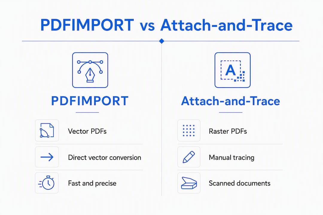
Zoom in past 400% in your PDF viewer. Crisp lines mean vector data. Pixelated edges mean raster. You can also try PDFIMPORT on a small area of the drawing — if AutoCAD brings in lines and text, you’re working with vector geometry. If it drops in an image, you have a raster PDF and need the attach-and-trace workflow instead.
The exact command flow
Open the target drawing in AutoCAD.
Go to the Insert tab on the Ribbon and click Import PDF in the Import panel — or type PDFIMPORT on the command line.
In the file dialog, select your PDF and click Open.
If the PDF has multiple pages, click the thumbnail for the page you need (or type the page number). For multi-page PDFs with complex layouts, import one page at a time to keep geometry manageable.
Set your options: choose which layers to import, whether to import text as editable text or as geometry, and whether to import solid fills.
Set the insertion point on-screen or accept the UCS origin (0,0). Placing at the origin keeps things predictable.
Click OK. AutoCAD converts the PDF geometry into lines, polylines, arcs, and text objects in the current drawing.
Per Autodesk’s official PDFIMPORT documentation, when the option to specify an insertion point is cleared, the PDF imports at the UCS origin — useful for drawings where you need predictable placement.
Post-import cleanup
After import, the geometry is often noisier than it looks. Run these commands in order:
PURGE — removes unused layers, blocks, and styles that came in with the PDF.
AUDIT — fixes structural errors in the drawing file.
PEDIT → Join — connects fragmented polyline segments into continuous paths.
EXPLODE — use sparingly, only when you need to break apart a block that came in as a grouped object and can’t be edited otherwise.
Pro Tip: If the PDF was already attached as an underlay before you ran PDFIMPORT, AutoCAD will prompt you to keep, detach, or unload the original underlay. Choose “Detach” unless you have a specific reason to keep it — an orphaned underlay reference adds file weight and can cause confusion when the drawing is shared.
How to attach a scanned PDF and trace it into reliable CAD geometry
Standard AutoCAD cannot convert raster scans into editable lines automatically — that’s not a limitation to work around, it’s just the reality of pixel-based images. Manual tracing is slower, but it produces the cleanest geometry and gives you full control over what ends up in the drawing.
Before you start: a quick checklist
Scan resolution: aim for 300 dpi or higher. Lower-resolution scans make snapping unreliable and tracing guesswork.
Deskew the image if the drawing is rotated or skewed — do this in your image editor before attaching, not after.
Identify a known reference dimension on the drawing (a wall length, a room width, a grid spacing). You’ll need this to scale correctly.
Create a dedicated tracing layer before you attach anything. Name it something obvious like TRACE-WORK, set it to a high-contrast color (cyan or yellow against a dark background works well), and keep the underlay on its own locked layer.
Attach, scale, and trace
Type PDFATTACH (or IMAGEATTACH for a TIFF or JPG) to attach the file. Place it roughly in the drawing area — exact position doesn’t matter yet.
Scale immediately: type SCALE, select the underlay, press Enter, pick a base point, then type R for Reference. Click the two endpoints of your known dimension on the underlay, then type the actual real-world length. AutoCAD scales the image to match.
Lock the underlay layer. You don’t want to accidentally move it mid-trace.
Start tracing with LINE, PLINE, ARC, and CIRCLE, using object snaps — Endpoint, Intersection, and Perpendicular — to keep geometry tight. Avoid Nearest snap during tracing; it attaches to the image pixels rather than logical geometry points.
Use JOIN or PEDIT → Join to close and combine segments as you go. Cleaning up open polylines at the end of a large trace is far more painful than closing them section by section.
When tracing is complete, freeze or turn off the underlay layer and review the traced geometry on its own.
Pro Tip: Work at a zoom level where individual line segments are clearly visible — roughly 1:1 on screen for most architectural drawings. Break long polylines into logical segments (one room boundary, one structural grid line) rather than trying to trace an entire floor plan as a single path. Shorter segments mean simpler PEDIT joins and easier corrections.
When does Autodesk Raster Design actually make sense?
Manual tracing is the right call for a single drawing or a small set of clean scans. When you’re looking at dozens of scanned pages, Autodesk Raster Design changes the math. It’s a separate install included with certain Autodesk subscriptions, and it adds raster-to-vector conversion tools directly inside AutoCAD.
The Raster Design workflow
Open the scanned PDF in Adobe Acrobat (or a similar viewer) and export the page as a TIFF file at 300 dpi or higher.
In AutoCAD with Raster Design installed, use Insert Image with the Insertion Wizard to attach the TIFF. This step activates the Raster Design toolset.
Use Raster Design’s vectorization tools to convert raster lines to AutoCAD geometry.
Export the result as DXF or DWG.
Open or insert that file into your working drawing, then rescale to a known reference and clean up.
Trade-offs worth knowing
Factor | Manual tracing | Raster Design / third-party converter |
Geometry quality | High — you control every line | Variable — doubled lines and jagged curves are common |
Speed | Slow for complex drawings | Fast for batch processing |
Scale accuracy | Exact (you set the reference) | Requires post-conversion rescaling |
Cleanup required | Minimal if traced carefully | Often significant |
Cost | No extra license needed | Subscription or purchase required |
Test any converter on a representative sample page before committing to a batch run.
Confirm your subscription tier includes Raster Design before purchasing a third-party tool.
Automated vectorization cannot invent real-world dimensions. No converter can recover sizes that were never recorded in the image — always rescale to a known reference after any automated conversion.
Third-party raster-to-vector tools vary widely in output quality. Run a sample conversion and measure a known distance before trusting the geometry.
Warning: Automated vectorization is a starting point, not a finished product. Expect to spend time on cleanup regardless of which tool you use.
Common problems after importing or tracing, and how to fix them
Wrong scale
This is the most common issue, and the fix is always the same: SCALE with the Reference (R) option. Select all the imported geometry, pick a base point, type R, click the two endpoints of a known dimension in the drawing, then type the correct real-world length. Everything rescales proportionally.
Missing or garbled text
Text from vector PDFs sometimes imports as SHX font geometry (a series of lines) rather than editable text. Check the import options before running PDFIMPORT — there’s a setting to import text as text objects. If critical dimensions came in as geometry, retype them. For raster PDFs, text is part of the image and won’t convert automatically; use OCR software on the PDF before attaching if you need editable annotations.
Heavy file size and duplicate geometry
Run PURGE first, then AUDIT. If the file is still bloated, check for duplicate overlapping lines with OVERKILL (available in AutoCAD’s Express Tools). Detach any underlays you no longer need — an attached PDF underlay that isn’t being used still adds file weight and can create broken external references when the drawing is moved or shared.
Broken polylines and jagged arcs
Use PEDIT → Join to reconnect fragmented segments. For curves that came in as short straight-line approximations, you have two options: use PEDIT → Fit or Spline to smooth them, or redraw the arc from scratch using ARC with three known points. Redrawn arcs are almost always cleaner than smoothed approximations from a raster conversion.
Pro Tip: Before running any major cleanup, save a copy of the imported layer set or create a snapshot layer group. If a cleanup command produces unexpected results, you can revert to the original imported state and try a different approach without starting over.
For a broader look at common AutoCAD drafting mistakes that show up after import, S15studio has a dedicated guide covering PURGE, AUDIT, and JOIN workflows in more detail.
Trainer-vetted tips for faster, cleaner AutoCAD tracing
These are the habits that separate a clean, reusable DWG from one that causes problems downstream.
Layer discipline. Always trace on a dedicated layer, never on the underlay layer or Layer 0. A well-named layer structure — TRACE-WALLS, TRACE-DIMS, TRACE-ANNOTATIONS — makes it easy to isolate, check, and hand off geometry. Lock the underlay layer the moment you start tracing.
Snap discipline. Endpoint, Intersection, and Perpendicular snaps are your accuracy tools. One misplaced snap point creates a gap or overlap that propagates through every downstream operation — hatching, dimensioning, area calculations. Turn off Nearest snap while tracing raster images; it latches onto pixel edges rather than logical geometry.
File management. Run PURGE and AUDIT before saving a file you plan to share or archive. Detach underlays after PDFIMPORT is complete. These two steps take under a minute and prevent the majority of “why is this file 80MB?” conversations.
Pro Tip: Build a tracing template: a DWT file with preset layer names, colors, and named views for common zoom levels. Save it once, load it at the start of every tracing job. Small setup rituals like this reduce repetitive configuration and keep trace quality consistent across projects.
Steve Fagan is an Autodesk Certified Trainer and the founder of S15studio. The AutoCAD drawing setup guide on the S15studio site covers layer templates and drawing standards in depth for architects and technicians who want a repeatable starting point.
Quick workflow checklists: which path should you take?
When to use PDFIMPORT | When to attach and trace (or use Raster Design) |
PDF was exported from CAD/BIM software | PDF is a scanned drawing or photograph |
Lines stay crisp when zoomed past 400% in a viewer | Lines pixelate when zoomed in |
You need editable text from the PDF | Text is part of the image (raster) |
Single-step conversion is the priority | Accuracy and geometry control are the priority |
Small to medium file, single page | Large batch of scanned pages (consider Raster Design) |
PDFIMPORT workflow (vector PDF)
Zoom test in PDF viewer — confirm vector geometry.
Open target drawing in AutoCAD.
Insert tab → Import PDF (or type PDFIMPORT).
Select file, choose page, set layer and text options.
Place at UCS origin or specify insertion point.
Run PURGE → AUDIT → PEDIT JOIN.
If underlay was attached, choose Detach when prompted.
Verify: measure one known dimension with DIST and confirm it matches the drawing.
Attach-and-trace workflow (raster PDF)
Confirm 300 dpi scan resolution; deskew if needed.
Identify a known reference dimension on the drawing.
Type PDFATTACH (or IMAGEATTACH for TIFF/JPG) and place the underlay.
SCALE → select underlay → R (Reference) → click known dimension endpoints → type real-world length.
Lock the underlay layer; create and activate your tracing layer.
Trace with LINE, PLINE, ARC, CIRCLE using Endpoint, Intersection, Perpendicular snaps.
JOIN / PEDIT JOIN to close segments as you go.
Freeze underlay layer and review traced geometry.
Verify: measure one known dimension with DIST and confirm scale is correct.
Key Takeaways
The single most important rule in AutoCAD PDF import and tracing: identify whether your PDF is vector or raster before you touch a command, then scale to a known reference dimension immediately after any import or attachment.
Point | Details |
Vector vs. raster decision | Vector PDFs use PDFIMPORT for direct conversion; raster PDFs require attach, scale, and trace. |
Scale immediately | Run SCALE with Reference ® right after attachment — skipping this makes all geometry architecturally useless. |
Cleanup is non-negotiable | Run PURGE and AUDIT after every import; use PEDIT JOIN and OVERKILL to fix duplicate or broken geometry. |
Automation needs verification | Raster Design and third-party converters speed batch work but always require rescaling and cleanup. |
S15studio training | S15studio’s project-based AutoCAD courses build these workflows through real drawing exercises, not isolated commands. |
Why these workflows matter more than most tutorials admit
Most PDF tracing tutorials focus on the commands and skip the reasoning. The commands are the easy part — PDFIMPORT is three keystrokes. What actually causes rework is the decision that happens before the command: is this a vector PDF or a raster PDF, and did I scale it correctly?
The scale step is where drawings quietly go wrong. A floor plan that looks right on screen but is 1.3% off in scale will produce area calculations, material takeoffs, and coordination models that are all wrong by the same margin. Nobody notices until the contractor measures on site. The fix — SCALE with Reference — takes 20 seconds. Skipping it costs hours.
The other thing practitioners underestimate is layer discipline during tracing. Drawing on the underlay layer or on Layer 0 seems harmless in the moment. Three months later, when someone else opens the file and tries to isolate walls from annotations, the geometry is unsortable. The habit of creating a named tracing layer before touching a single line pays back every time the file is reused.
Automated vectorization tools, including Raster Design, are genuinely useful for volume work. But they are a starting point, not a finished product. The geometry they produce almost always needs a human pass to fix doubled lines, close open paths, and confirm scale. Treating converter output as final-quality geometry is the most common mistake in raster-to-vector workflows.
S15studio AutoCAD training: build these skills through real project practice
Knowing the commands is one thing. Knowing which command to reach for, in which situation, without hesitating — that comes from practice on real drawings.
S15studio’s AutoCAD course covers PDF import, tracing workflows, layer standards, and cleanup techniques through project-based exercises built around actual architectural drawings. You get trainer feedback from Steve Fagan, downloadable templates, and lifetime access to materials — so you can revisit a workflow the moment a tricky PDF lands on your desk. For professionals who also work in Revit, the complete Revit and AutoCAD training bundle covers both platforms with the same project-based approach. Pick the course that matches where you are now and start building the habits that prevent rework.
Useful sources and official references
These links go directly to official Autodesk documentation and practitioner guides used as evidence throughout this article. Official docs are the most reliable source for command syntax and option details; practitioner tutorials are useful for workflow context and real-world tips.
To Work with Importing PDF Data — Official Autodesk help documentation for the PDFIMPORT command, including dialog options and page selection.
How to Import a PDF Into AutoCAD — Autodesk blog walkthrough of the PDFIMPORT workflow with Ribbon and command-line paths.
How to Convert a PDF to a DWG in AutoCAD Products — Autodesk support article covering PDFIMPORT, third-party tools, and the history of PDF underlay support before AutoCAD 2017.
Attaching a PDF Underlay Versus Importing a PDF File — Autodesk tutorial explaining when to attach versus import and the practical difference between the two approaches.
When PDF Import Isn’t an Option… AutoCAD Raster Design! — Autodesk blog post on Raster Design’s role in the raster-to-vector workflow, including the PDF-to-TIFF conversion step.
The Ins and Outs of PDFs and AutoCAD — Autodesk blog covering underlay management, keep/detach decisions, and file-size considerations.
How to Trace/Digitize Any Sketch or PDF in AutoCAD (The Smart Way) — Practitioner tutorial emphasizing layer management and reference-line discipline for tracing workflows.
— Video walkthrough demonstrating the Insert tab UI sequence and reference-point placement for visual learners.
Before batch-processing a large set of PDFs, test your chosen workflow on a single representative page. Confirm scale with DIST on a known dimension, check geometry quality, and only then scale up to the full set.
Recommended