
How to Set Up AutoCAD Point Cloud Integration
- Steve Fagan

- 32 minutes ago
- 9 min read

AutoCAD natively supports point cloud files in the RCS and RCP formats, and you attach them with a single command: POINTCLOUDATTACH. That’s the whole entry point. Once a scan is in your drawing, the Point Cloud contextual tab and Point Cloud Manager give you control over which scans and regions are visible, and PCEXTRACTSECTION turns a slice of that scan into usable 2D linework you can dimension and finalize.
Here’s what to know before you open a project:
AutoCAD reads RCP (project) and RCS (scan) files built by Autodesk ReCap, not raw scanner output.
POINTCLOUDATTACH inserts the file; the resulting contextual tab exposes density, clipping, and color stylization controls immediately.
PCEXTRACTSECTION generates DWG geometry from a section plane you define.
Node object snap lets you snap directly to individual scan points while drafting.
This is a workflow S15Studio teaches directly in its AutoCAD training, built by Autodesk Certified Trainer Steve Fagan for architects and engineers who need scan-to-drawing skills that hold up on real projects.
Key Takeaways
Successful AutoCAD point cloud integration depends on preprocessing in ReCap, disciplined use of POINTCLOUDATTACH and PCEXTRACTSECTION, and clipping strategy over raw hardware power.
Point | Details |
Use the right file format | Attach RCP or RCS files only; convert E57 or LAS scans through ReCap first. |
Master three core commands | Learn POINTCLOUDATTACH, PCEXTRACTSECTION, and Node snap before starting a project. |
Organize before you draft | Use Point Cloud Manager to rename scans, toggle visibility, and build clipping boxes early. |
Prioritize structure over hardware | Octree partitioning and streaming chunks matter more than raw processing power. |
Always QA extracted geometry | Verify dimensions against known references before finalizing any drawing. |
Table of Contents
Pre-Session Checklist Before You Attach a Point Cloud
Five minutes of prep here saves you from reattaching files halfway through a session.
Confirm your file type. You need an RCP or RCS file. If your scanner exported E57 or LAS, run it through ReCap first to convert it.
Check units and geolocation. Mismatched units between the scan and your drawing template cause silent scaling errors that are painful to trace later.
Decide on locking. If you don’t want the cloud nudged accidentally during drafting, lock it once positioned.
Close unnecessary background apps and set point density low before you attach anything heavy.
Create a clipping box early rather than working with the full unclipped dataset.
Know your three core commands going in: POINTCLOUDATTACH, PCEXTRACTSECTION, and Node snap.
Pro Tip: Set density to its lowest setting the moment you attach a large scan, get your clipping box and viewport oriented first, then bump density back up only for the region you’re actively drafting.
How Do You Attach an RCS or RCP Point Cloud in AutoCAD?
Open the Insert tab, go to the Reference panel, and choose Attach, or just type POINTCLOUDATTACH at the command line. Either path opens the same file browser.
Select your RCP or RCS file. If you’re working from a ReCap project with multiple scans, the RCP file is usually the better choice since it references the individual RCS files as one coordinated project rather than forcing you to attach each scan separately.
From there, Autodesk’s attachment workflow asks you to set:
Insertion point — where the cloud’s origin lands in model space.
Scale — usually left at 1:1 if units match, but worth verifying before you commit.
Rotation — align the scan to your drawing’s north or grid orientation.
Two checkboxes matter more than they look. Lock Point Cloud prevents the attached scan from being moved, scaled, or rotated by accident during later edits, which is worth turning on the moment you’ve confirmed placement. Use Geographic Location only works if both your drawing and the point cloud carry matching coordinate system data. If either file lacks that metadata, AutoCAD ignores the option rather than erroring out, so don’t count on it as your primary alignment method.
Once attached, the Point Cloud contextual tab appears automatically on the ribbon. This is where you’ll spend most of your time: density sliders control how many points render (critical for performance), color stylization lets you switch between RGB, intensity, and elevation views, and clipping controls let you box off exactly the region you’re working in. All three are one click away, not buried in a dialog.
Managing Scans and Regions Without Losing Your Place
Large scan-to-BIM projects can involve dozens of individual scans, and getting lost inside a dense cloud is the single most common frustration new users report. The fix is the Point Cloud Manager, accessible from the contextual tab’s Options panel.
Inside the manager, you can:
Toggle individual scans or regions on and off to isolate what you’re currently drafting.
Rename scans and regions with descriptive labels (floor level, room number, elevation angle) instead of the default scanner filenames.
Use the built-in search to jump straight to a named scan in a project with dozens of them.
Build clipping boxes around active work areas so the viewport only renders what’s relevant, which noticeably reduces lag on dense datasets.
One feature gets overlooked constantly: double-clicking a scan in the manager jumps your viewpoint directly to the scanner’s original camera position. That’s an underused fix for the “I don’t know where I am in this cloud” problem, and it pairs well with a clipping box you’ve already set up, since you land back in context immediately instead of orbiting blindly.
Pro Tip: Rename every scan the moment you attach it. A project with fifteen scans labeled “Scan_001” through “Scan_015” is unmanageable two weeks later, even to the person who set it up.
From there, use 3DORBIT, 3DWALK, or 3DSWIVEL to reorient yourself once you’ve landed at the right camera position.
Turning a Point Cloud Into Drawable Geometry
Extraction is where a point cloud actually becomes a drawing. PCEXTRACTSECTION is the command that makes this possible.
Define your section plane. Position it through the part of the scan you want converted, a wall face, a floor slab, a pipe run.
Run PCEXTRACTSECTION and select the point cloud. AutoCAD analyzes the points near that plane and generates 2D linework on a plane coincident with your section by default.
Snap to individual points using Node object snap while cleaning up the extraction. Keep in mind that Node snap is viewpoint-dependent. It snaps to the point nearest your current view angle, not necessarily the point you’d hit from a different orientation, so verify snaps from more than one view when precision matters.
Layer the extracted geometry separately from your working drawing so you can toggle it independently and QA it against the original scan.
Verify dimensions against known references (door widths, structural grid, existing drawings) before you trust the extraction.
Clean up manually where the algorithm misreads noisy or overlapping points. Automated extraction handles planar and cylindrical surfaces well, but a corroded steel beam or an irregular masonry edge often needs a human pass.
That five-step sequence, section, extract, layer, verify, finalize, is the backbone of scan-to-drawing work, and it holds whether you’re documenting an existing building or verifying as-built conditions against design intent. For a deeper look at pulling structured data out of AutoCAD drawings generally, see this breakdown of AutoCAD data extraction.
Why Performance Problems Are Usually a Structure Problem
A point cloud with tens of millions of points doesn’t need a supercomputer. It needs better organization. Efficient handling comes down to structural strategies like octree partitioning and streaming rather than raw processing power, and octree structures alone can cut memory demands substantially by loading only the point density a given view actually needs.
Three habits keep AutoCAD responsive on real projects:
Register, clean, and segment scans inside ReCap before you ever attach anything to AutoCAD. ReCap’s segmentation identifies planar and cylindrical surfaces, which speeds up extraction later and cuts down on noise.
Lower density and set clipping boxes the moment you attach a scan, then raise density only in the region you’re actively editing.
For datasets in the hundreds of millions of points, offload heavy registration and classification work to preprocessing tools or cloud services rather than trying to force AutoCAD to carry that load directly.
Streaming chunks mean AutoCAD only loads what’s visible in your current clip and view, not the entire dataset at once. That’s why a well-prepared 500-million-point project can feel lighter than a poorly organized 50-million-point one.
RCS, RCP, E57, and LAS: Which Format Do You Actually Need?
RCS and RCP are Autodesk’s own optimized formats, purpose-built for fast loading and rendering inside AutoCAD and Revit. E57 and LAS are open, vendor-neutral formats most scanners export natively, useful for interchange between different software packages but not directly readable by AutoCAD.
That’s where ReCap sits in the pipeline. It converts raw E57 or LAS scanner output into RCS and RCP, and lets you segment a project into regions so you can import only the section relevant to your current task instead of the whole site.
For tools beyond ReCap itself, think in categories rather than brand names:
Registration tools align multiple scan positions into one coordinate system.
Vectorization and conversion utilities handle format translation and initial geometry cleanup.
Cloud streaming platforms manage massive datasets remotely so local hardware isn’t the bottleneck.
Scripting libraries like PDAL support programmatic, repeatable preprocessing pipelines for teams handling recurring scan batches.
Once you’ve extracted geometry in AutoCAD, standard export options apply: DWG for the 2D linework itself, or OBJ and FBX if you’re pushing a derived 3D model into another modeling or visualization package.
What S15Studio Teaches Students About Point Cloud Work
A few habits separate students who pick this up fast from those who fight AutoCAD for weeks.
Align your UCS to a planar surface in the scan before drafting. Working off a tilted or arbitrary UCS is the single biggest source of frustrating extraction errors.
Use the camera-jump feature in Point Cloud Manager constantly, not just when you’re lost.
Check units before attaching, not after. It’s a thirty-second check that prevents an hour of troubleshooting.
Don’t overimport. Attach only the regions relevant to your current task instead of the entire project.
Always QA your extraction against a known dimension before you build on top of it.
These are the exact fundamentals covered in S15Studio’s AutoCAD training, built around real project workflows rather than isolated command demos. For students still building baseline AutoCAD skills, this primer on what architecture students need to know is a solid starting point before tackling point cloud work.
Get Trained on the Full Scan-to-Drawing Workflow
Reading through these commands is one thing. Applying them under a real project deadline, with a messy scan and a client waiting on drawings, is another. S15Studio’s complete Revit and AutoCAD training walks through this exact scan-to-drawing pipeline as part of its project-based curriculum, taught by Autodesk Certified Trainer Steve Fagan, with lifetime access to course materials and direct trainer support. If you’re still solidifying core AutoCAD skills before tackling point clouds, the beginner-to-advanced AutoCAD course builds that foundation first.
Point Cloud Editorial Perspective
Most tutorials treat point cloud attachment as the hard part. It isn’t. POINTCLOUDATTACH takes thirty seconds once you know where the file lives. The actual skill gap shows up two steps later, when a student has a 200-million-point scan on screen and no plan for isolating what matters.
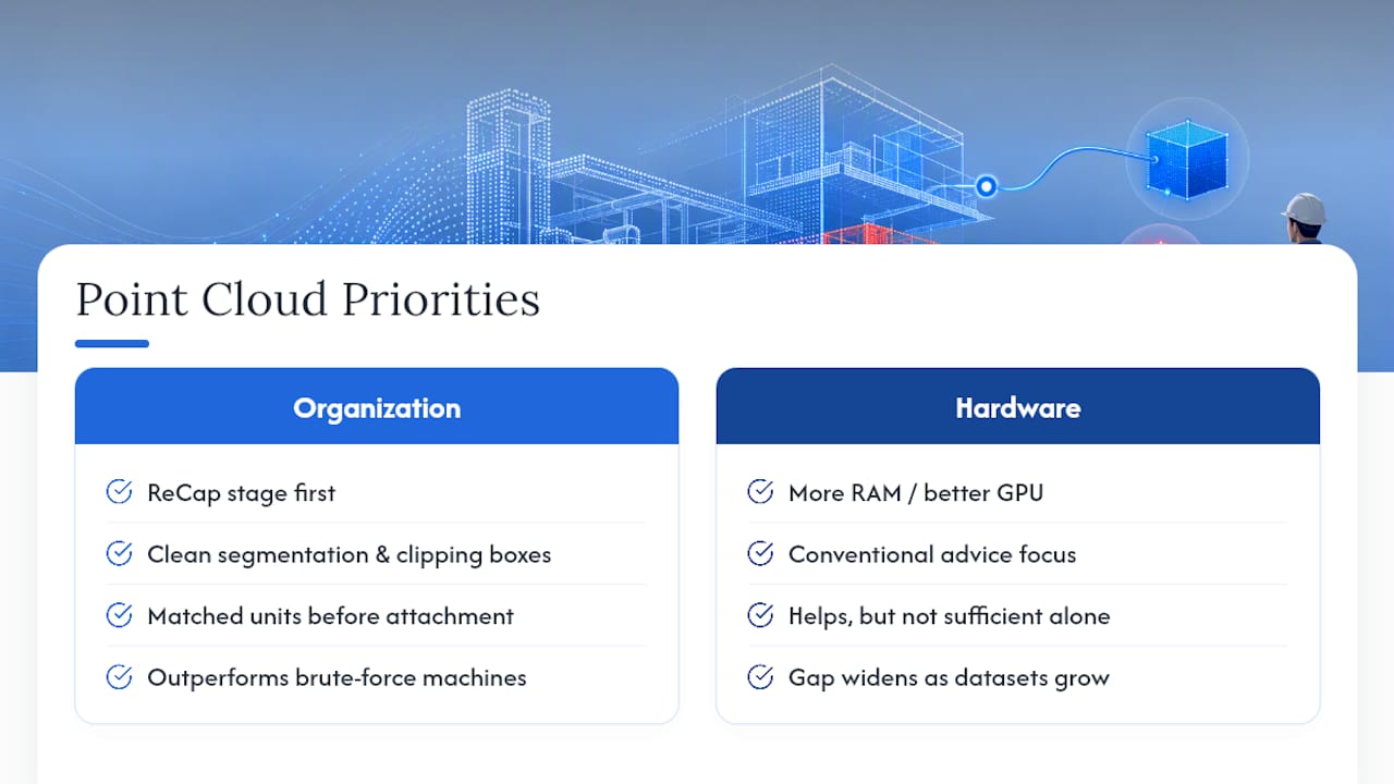
Conventional advice leans hard on hardware: buy more RAM, get a better GPU. That’s backwards. Organization beats horsepower almost every time. A well-segmented ReCap project with tight clipping boxes will outperform a brute-force machine running an unsegmented mess, and that gap only grows as datasets get bigger.
If you take one thing from this, prioritize the ReCap stage over the AutoCAD stage. Clean segmentation, sensible regions, and matched units before attachment prevent nearly every headache people blame on AutoCAD itself. The command names are the easy part. Discipline upstream is what actually separates a smooth scan-to-drawing project from a frustrating one.
Frequently Asked Questions About AutoCAD Point Cloud Integration
Does AutoCAD support point cloud files directly? Yes. AutoCAD reads RCP and RCS files natively, both created through Autodesk ReCap from raw scanner data like E57 or LAS.
What command do I use to attach a point cloud in AutoCAD? Type POINTCLOUDATTACH at the command line, or go to Insert > Reference > Attach and select your RCP or RCS file.
How do I extract 2D drawings from a point cloud? Define a section plane through the area you need, then run PCEXTRACTSECTION. AutoCAD generates DWG linework on a plane matching your section by default.
Why does AutoCAD slow down with large point cloud files? Unclipped, high-density scans force AutoCAD to render far more data than the viewport needs. Lower density, build clipping boxes early, and preprocess with ReCap’s segmentation to keep performance manageable.
Can I combine multiple scans into one AutoCAD project? Yes. Attach the RCP project file rather than individual RCS files, since RCP references multiple scans as one coordinated dataset you can manage through Point Cloud Manager.
Sources
Recommended
Comments