
Datum First Revit Reference Planes: 5 Steps for Architects & BIM Pros


A reference plane is an infinite datum you place in a project or family to control alignment, snapping, and dimensioning. The rule that saves the most rework: name every reference plane, set its Is Reference priority deliberately, and reach for a reference line instead whenever you need rotation or a defined endpoint. The sections below walk through properties, creation steps, and the checks that catch mistakes before they reach a client model.
TL;DR:
Assign strong reference priority to core geometry edges to ensure they serve as reliable dimensioning and snapping anchors during family edits.
Use reference lines instead of planes when you need to incorporate rotation or instance-driven shape handles, as they provide multiple work planes and endpoints.
Name reference planes immediately after creation, organize them with subcategories, and lock them to relevant geometry to maintain a clean, predictable datum set.
Hide or organize reference planes using subcategories and scope boxes to prevent clutter and improve clarity in views without losing essential alignment data.
Verify family stability by swapping types and flexing parameters to confirm that geometry and snap points respond as intended before finalizing design.
Table of Contents
What are reference planes and when should you use them?
A reference plane is a flat, infinite datum that shows up in plan and elevation views and can double as a work plane for sketching geometry. In a project file it behaves like a lightweight grid line: useful for aligning walls or setting up a section, but rarely central to the model’s logic. Inside the Family Editor, reference planes carry far more weight. They form the skeleton that geometry locks to, so swapping a type or flexing a parameter moves the model predictably instead of breaking it.
Typical uses include:
Anchoring dimensions and alignment points that stay fixed as a family flexes.
Controlling wall layer wrap in wall-based families.
Setting a sketch plane for extrusions, sweeps, or nested components.
Treat the project use as convenience and the family use as structure: get the datum layout right before you draw a single line of geometry.
Reference plane properties and the ‘Is Reference’ priority
Every reference plane has properties on the Properties palette, including Name, Subcategory, Scope Box, and Is Reference, which controls whether the plane can be used for dimensioning and snapping. The Is Reference setting offers Strong Reference, Weak Reference, or Not a Reference, and Weak Reference is the default for new planes.
Strong references take priority over other snap points and are the first thing a temporary dimension will snap to, which is why assigning them carelessly causes dimensions to lock onto the wrong edge during family loading.
A short checklist before you finalize a family:
Set core geometry edges (centers, faces used in schedules) to Strong Reference.
Leave secondary or cosmetic planes as Weak Reference so they don’t compete for snaps.
Reserve Not a Reference for construction guides that should never appear in dimension strings.
How to create, name, and organize reference planes
Building a clean datum set takes a handful of consistent steps every time.
Draw the plane with the Line tool, or use Pick Lines to snap to existing geometry and set an offset on the Options bar.
Lock the plane to a wall face, grid, or edge when it needs to stay fixed as the model changes.
Name it immediately in the Properties palette, using a convention that matches its role (for example, “Center Left” or “Door Frame Face”).
Assign a subcategory so the plane can be isolated or hidden as a group later.
Apply a scope box if the plane should only display in a defined set of views.
Pro Tip: Name reference planes before you sketch anything against them: an unnamed plane is nearly impossible to pick out of a crowded family once geometry surrounds it.
Reference plane vs reference line: when to choose each

A reference plane is a single infinite plane with no endpoints. A reference line is a datum object that provides multiple work planes along its length, plus defined endpoints, and you cycle between its planes with the Tab key.
That distinction decides which one to pick:
Use a reference plane for static alignment: centers, faces, and fixed dimension anchors.
Use a reference line whenever the family needs to rotate, such as a swinging door leaf or a pivoting elbow fitting.
Use a reference line when you need an instance parameter driving a shape handle, since its endpoint geometry supports that behavior more naturally than a flat plane.
A door swing built on a reference plane will fight you the moment you try to add an angle parameter. Build it on a reference line from the start and the rotation behaves as expected.
Controlling visibility: subcategories, Hide in View, and scope boxes
Reference planes are hidden by default in most project views, but family authors and coordinators still need finer control once a model gets busy. You can select an individual plane and apply Hide in View, or turn off the entire Reference Planes category in Visibility/Graphics when none of them should show.
Hide in View works for a one-off case where a single plane clutters a specific sheet.
Subcategories let you group related planes (layout, structural, cosmetic) and toggle them together across every view.
Scope boxes limit how far a datum extends, keeping long reference planes from bleeding into views where they add no value.
Setting up subcategories early, rather than retrofitting them into a finished family, keeps documentation consistent across every sheet that references the model.
Practical family workflow and common mistakes to avoid
A reliable family build follows the same order every time, and skipping steps is where most reference-plane problems start.
Lay out the datum: place and lock all reference planes before adding any geometry.
Name every plane using a convention you can scan quickly in a crowded parameter list.
Sketch and lock geometry to the named planes, not to arbitrary points.
Set Is Reference priorities on the planes that matter for dimensioning and scheduling.
Test the family by swapping types and flexing parameters to confirm geometry moves as intended.
Common mistakes include leaving planes unnamed (which makes later edits a guessing game), setting Strong Reference on planes that should stay in the background, and trying to force rotation out of a plane instead of switching to a reference line.
Pro Tip: Always verify a finished family by swapping sizes or types and checking that temporary dimensions and align snapping land on the intended strong references, since this single check catches most reference-related bugs before they reach a project.

Quick troubleshooting checklist and shortcuts
When a work plane or alignment isn’t behaving, run through a short list before rebuilding anything.
Open the Work Plane dialog and choose Name or Pick a Plane rather than relying on the automatic default, especially in section or elevation views.
Use Tab to cycle through the multiple work planes available on a reference line’s endpoints.
If a dimension snaps to the wrong edge, check whether the intended plane is set to Weak Reference and needs to be Strong instead.
Rename any plane that shows up as a generic “Reference Plane” label in the parameter list.
Reapply a scope box if a datum is showing up in views where it shouldn’t.
How S15Studio teaches reference plane workflows
We build every Revit lesson around project work rather than theory, so learners practice the datum-first sequence on real families, not isolated exercises. Checkpoints along the way include swap tests and dimension checks, the same verification habits outlined above. A good starting exercise: build one simple family using named reference planes before adding a single piece of geometry.
— Steve
Learn these workflows in a structured Revit course
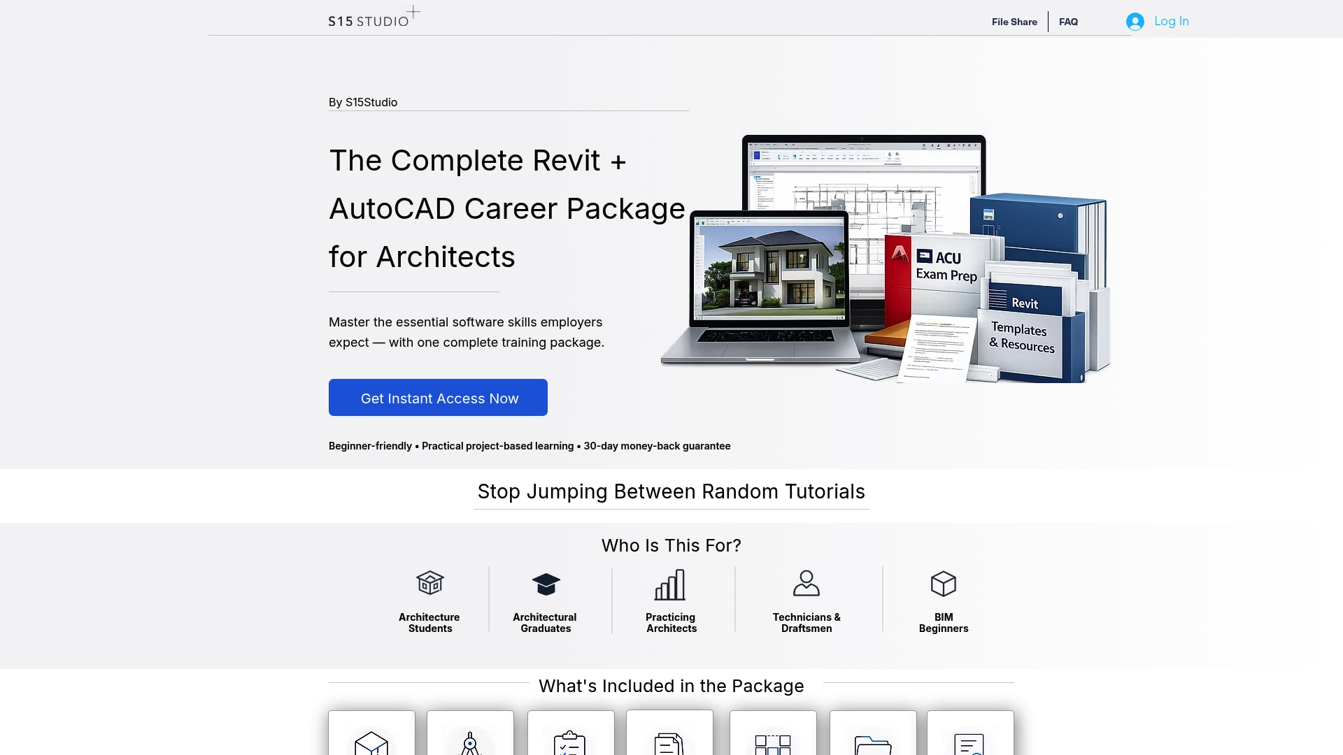
Reading through the steps above gets you the logic, but building the habit takes repetition with feedback on your own files. The Revit Course Only at S15Studio covers family authoring from the ground up, including datum layout, naming conventions, and the Is Reference decisions that keep complex families stable, for a one-off fee. Learners who want to push further into nested families and shared parameters can move on to the Advanced Course, available for a one-off fee.
Both paths include:
Project-based exercises built around real family and project scenarios.
Direct trainer feedback on your submitted work.
Direct trainer feedback on your submitted work.
Lifetime access to course materials and a completion certificate.
If you are new to Revit family creation entirely, our step-by-step family guide is a useful companion while you work through the course. Start with the Revit Course Only to build the fundamentals properly.
Sources
FAQ
How do I create a reference plane in Revit?
Use the Reference Plane tool and either draw a line directly or use Pick Lines to snap to existing geometry, with offsets available on the Options bar. Name the plane right away in the Properties palette so it stays identifiable once other geometry surrounds it.
What is the difference between a reference line and a reference plane?
A reference plane is a single infinite flat datum with no endpoints, while a reference line has defined endpoints and provides multiple work planes you can cycle through with Tab. Choose a reference line whenever a family needs rotation or a shape handle driven by an instance parameter, and a reference plane for static alignment.
How do I turn off reference planes in a view?
Select an individual plane and apply Hide in View for a one-off case, or open Visibility/Graphics and turn off the entire Reference Planes category to remove them all at once. Assigning subcategories in advance makes it easier to toggle related groups of planes together later.
What is a reference plane used for?
A reference plane acts as a datum for alignment, snapping, and dimension anchoring in both project files and families. In family authoring, it also defines the work planes that geometry sketches against, making it central to how a family flexes when types or parameters change.
How does the Is Reference setting affect dimensioning?
Is Reference determines whether a plane can be used for snapping and dimensioning, with options for Strong Reference, Weak Reference, or Not a Reference, and Weak is the default. Strong references take priority over other points, so temporary dimensions snap to them first when a family loads into a project.
Recommended
Comments