
AutoCAD Isometric Drawing Guide for Design Pros


AutoCAD isometric drawing is the process of producing 2D illustrations that simulate 3D views by aligning drawing tools to three isometric planes at 120-degree angles. This technique is the standard method architects and engineers use when they need measurable, undistorted representations of objects without switching to full 3D modeling. Unlike perspective drawings, isometric projection maintains constant scale, which means every measurement you read off the drawing is accurate. AutoCAD supports this workflow natively through the ISODRAFT command, the ELLIPSE Isocircle option, and the Ctrl+E shortcut. This autocad isometric drawing guide covers every step from initial setup to advanced shortcuts, so you can produce professional results on your first attempt.
What are AutoCAD isometric planes and how do you set them up?
AutoCAD’s isometric drafting environment is built around three planes: Top, Left, and Right. Each plane controls the orientation of your cursor and constrains lines to the correct isometric axes. ISODRAFT activates the isometric grid and locks the cursor to those three planes, replacing the standard rectangular snap with an angled one. Getting this setup right before you draw a single line saves significant rework later.
To activate isometric drafting, follow these steps:
Type ISODRAFT at the command line and press Enter. AutoCAD switches the grid and cursor to isometric mode immediately.
Alternatively, type SNAP, select Style, then choose Isometric. This sets the SNAPSTYLE system variable to isometric mode manually.
Confirm the grid has shifted to a diamond pattern. That visual change confirms the isometric snap is active.
Use Ctrl+E to cycle between the Top, Left, and Right isoplanes. The status bar displays the active plane name.
Check the SNAPANG system variable is set to 0. A non-zero value rotates the entire isometric grid and causes alignment errors.
Each isoplane controls a different face of your object. The Top plane draws the upper face, the Left plane draws the left vertical face, and the Right plane draws the right vertical face. Switching planes incorrectly is the most common cause of distorted isometric drawings among beginners.
Pro Tip: Save a drawing template with ISODRAFT already active and your preferred grid spacing set. Opening that template at the start of every isometric project eliminates the setup step entirely and keeps your settings consistent across files.

How do you draw basic shapes and lines in isometric mode?
Drawing in isometric mode requires a specific sequence of commands and plane selections. The Line command works exactly as it does in standard 2D drafting, but the cursor snaps only to isometric angles: 30, 90, and 150 degrees. Every line you draw must align to one of those angles or it will look wrong in the final view.
Follow this sequence to draw a basic isometric cube:
Activate ISODRAFT and set the isoplane to Left using Ctrl+E.
Type L for Line and click a start point. Draw a vertical line upward for the left edge of the cube.
Draw a line at 30 degrees to the right for the bottom edge of the left face.
Close the left face by drawing back to the start point.
Press Ctrl+E to switch to the Right isoplane. Draw the right face using the same method, starting from the shared right edge.
Press Ctrl+E again to switch to the Top isoplane. Draw the top face connecting the upper edges of both vertical faces.
Circles require a completely different approach. Standard circle commands distort geometry in isometric views because they produce true circles, not ellipses aligned to the isometric plane. The correct method uses the ELLIPSE command with the Isocircle option.
Shape | Command | Key setting |
Line | LINE (L) | Active isoplane must match face being drawn |
Circle | ELLIPSE > Isocircle | Isoplane must match the face the circle sits on |
Rectangle | LINE (four segments) | Switch isoplane between horizontal and vertical edges |
Arc | ELLIPSE > Isocircle > partial | Draw full isocircle, then trim to arc shape |
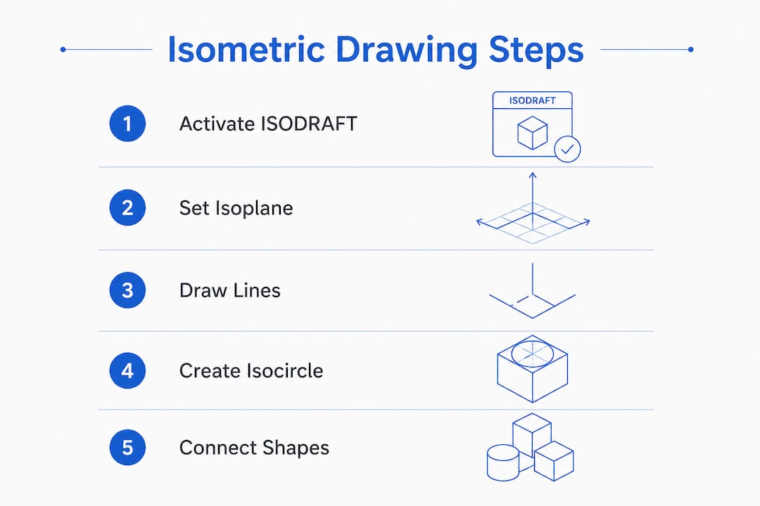
To draw an isocircle, type EL for Ellipse, then type I to select the Isocircle option. Specify the center point and radius. AutoCAD draws an ellipse that looks like a correct circle on the active isometric plane. Switch to the matching isoplane before drawing each isocircle, or the ellipse will tilt in the wrong direction.
Pro Tip: When drawing a cylinder in isometric, draw the bottom isocircle first, copy it vertically to the top, then connect the two with tangent lines on the left and right edges. This method is faster and more accurate than constructing the shape from scratch.
Common mistakes and how to troubleshoot isometric drawings
The single most damaging misconception in isometric drafting is treating it as 3D modeling. Isometric drawing is a 2D simulation that uses snap and grid constraints to mimic depth. Using 3D commands like EXTRUDE or BOX inside an isometric drawing adds unnecessary complexity and produces results that cannot be edited with standard 2D tools.
A second major source of errors is confusing Ortho mode with Isometric Snap. Ortho mode restricts cursor movement to 0 and 90 degrees, which is correct for standard 2D drafting but wrong for isometric work. When Ortho is active without ISODRAFT, your lines snap to horizontal and vertical only. The drawing looks flat and misaligned. Always confirm ISODRAFT is active before drawing, and check the status bar to verify the current isoplane.
Confusion between Ortho mode and Isometric Snap is one of the most common errors professionals see in student work. Deliberate mode management, checking the status bar before every line, is the habit that separates accurate drafters from frustrated ones.
Additional issues to watch for:
Wrong isoplane selected. A line drawn on the Left isoplane when it should be on the Right isoplane will angle in the wrong direction. Always confirm the active plane before starting each face.
Distorted circles. Using the CIRCLE command instead of ELLIPSE with Isocircle produces a round circle that looks wrong in isometric context. Delete it and redraw using the correct method.
Misaligned edges. Edges that should meet at a corner often miss by a small gap. Zoom in frequently during drafting to catch these gaps before they compound across the drawing.
Incorrect snap settings. If lines are not snapping to isometric angles, type SNAP and verify the style is set to Isometric, not Standard.
For a broader look at errors that affect all types of AutoCAD work, the common AutoCAD drafting mistakes guide from S15studio covers fixes that apply directly to isometric workflows.
Advanced tips and shortcuts for faster isometric drawing
Speed in isometric drafting comes from reducing the number of steps between decisions. The Ctrl+E shortcut is the most important habit to build. Ctrl+E cycles through all three isoplanes without interrupting an active command, which means you can switch planes mid-drawing without restarting the Line or Ellipse command. Expert AutoCAD users cycle planes instinctively, keeping their hands on the keyboard and their eyes on the drawing.
Layer organization is the second major efficiency gain. Most experienced drafters create separate layers for each isoplane: one for Top face geometry, one for Left, and one for Right. This structure makes it easy to isolate and edit a single face without affecting the rest of the drawing. It also speeds up plotting when you need to print specific views.
Additional techniques worth adopting:
Use object snap (OSNAP) consistently. Endpoint and intersection snaps prevent the small gaps that cause alignment errors across a complex drawing.
Create a dedicated isometric template. Set ISODRAFT, configure your layers by isoplane, set your drawing units, and save the file as a DWT template. Every new isometric project starts from a clean, correctly configured base.
Copy and mirror geometry. Symmetrical objects like pipes and brackets share geometry across faces. Draw one face completely, then copy or mirror it to the opposite side rather than redrawing from scratch.
Use the TRIM command after isocircles. When drawing partial arcs or cutouts, draw the full isocircle first, then trim away the unwanted portion. This approach is faster than trying to draw a partial ellipse directly.
Understanding the difference between AutoCAD 2D and 3D drafting also helps you decide when isometric is the right tool and when full 3D modeling is worth the extra setup time.
Pro Tip: Set your AutoCAD drawing units to match your project standard before activating ISODRAFT. Isometric snap spacing is tied to drawing units, and a mismatch between your snap grid and your intended scale causes measurement errors that are difficult to trace later.
Key Takeaways
Accurate AutoCAD isometric drawing requires ISODRAFT for plane control, ELLIPSE Isocircle for circles, and Ctrl+E for fast plane cycling, with all work kept in 2D space.
Point | Details |
Activate ISODRAFT first | Type ISODRAFT before drawing to lock the cursor to the three isometric planes. |
Use ELLIPSE for circles | The Isocircle option is the only correct way to draw circles in isometric view. |
Cycle planes with Ctrl+E | Press Ctrl+E to switch between Top, Left, and Right isoplanes without stopping a command. |
Keep all work in 2D | Isometric drawing simulates depth in 2D space; 3D commands add errors, not accuracy. |
Zoom frequently | Regular zooming catches misaligned edges and gaps before they affect the whole drawing. |
Why I think most AutoCAD users learn isometric drawing backwards
Most tutorials teach isometric drawing as a series of commands to memorize. That approach produces users who can follow steps but freeze the moment something goes wrong. The real skill is understanding why each setting exists.
The isoplane system exists because AutoCAD’s cursor is rectangular by default. ISODRAFT overrides that default and forces the cursor to behave like it lives on a tilted surface. Once you internalize that, troubleshooting becomes obvious. A line going the wrong direction means the wrong plane is active. A circle looking wrong means you used the wrong command. The fix is always logical.
I also see a lot of drafters skip the template step. They set up ISODRAFT manually every session, which wastes time and introduces inconsistency. A properly configured template with named layers, correct units, and ISODRAFT active is the single biggest productivity gain available to someone who draws isometric regularly. It takes 20 minutes to build and saves hours over a career.
The AutoCAD for architecture fundamentals covered at S15studio reinforce exactly this mindset: understand the tool, then use it efficiently. Isometric drawing is not a special skill separate from general AutoCAD proficiency. It is a direct extension of understanding how AutoCAD controls cursor behavior and snap geometry.
— Steve
Build your AutoCAD skills with S15studio
Isometric drawing is one technique inside a much larger AutoCAD skill set. S15studio offers structured training from beginner to expert level, built around real architectural and engineering projects rather than isolated exercises.

The complete AutoCAD training program at S15studio covers 2D drafting, isometric techniques, drawing standards, and project workflows in a single learning path. For those ready to add Revit to their skill set, the Revit introduction course provides a practical foundation that connects directly to the AutoCAD knowledge you already have. Both courses are project-based and designed for design professionals who need skills they can use immediately.
FAQ
What is AutoCAD isometric drawing?
AutoCAD isometric drawing is a 2D drafting method that simulates a 3D view by aligning lines and shapes to three axes spaced 120 degrees apart. It uses AutoCAD’s ISODRAFT command and snap settings rather than 3D modeling tools.
How do I activate isometric mode in AutoCAD?
Type ISODRAFT at the command line and press Enter. Alternatively, type SNAP, select Style, and choose Isometric to set the snap grid manually.
What is the difference between Ortho mode and isometric snap?
Ortho mode restricts the cursor to 0 and 90 degrees, which is correct for standard 2D drafting but incompatible with isometric work. Isometric snap aligns the cursor to 30, 90, and 150-degree angles to match the three isometric planes.
How do I draw circles correctly in isometric view?
Use the ELLIPSE command and select the Isocircle option, then specify the center and radius. Standard circle commands produce round circles that look distorted in isometric projection.
What does Ctrl+E do in AutoCAD isometric drawing?
Ctrl+E cycles the active isoplane between Top, Left, and Right without interrupting the current drawing command. It is the fastest way to switch planes during active drafting.
Recommended
Comments