
AutoCAD Mirror Command: Quick Guide for Beginners
- Steve Fagan

- 1 day ago
- 11 min read
The AutoCAD MIRROR command creates a symmetrical, reversed copy of selected objects across a user-defined mirror line. To use it: type MI and press Enter (or go to Home > Modify > Mirror), select your objects and press Enter, pick two points to define the mirror line, then answer the Erase source objects? [Yes/No] prompt. Press Enter to keep the originals (the default), or type Y to remove them. According to the AutoCAD Help documentation, MIRROR is available from the Home tab’s Modify panel or directly at the command line.
A few things to know before you start:
The source objects are kept by default. You have to actively choose to erase them.
Text readability is preserved by default (MIRRTEXT = 0), so your annotations won’t flip backwards unless you change that setting.
Hatch pattern behavior is controlled separately by the MIRRHATCH variable.
For 3D geometry, use MIRROR3D instead — it mirrors across a plane, not a line.
Pro Tip: If you’re new to AutoCAD’s editing commands, the getting started with AutoCAD guide from S15studio covers the core command structure you’ll need before diving into modify tools like MIRROR.
Key Takeaways
The AutoCAD MIRROR command creates a precise, symmetrical copy of selected objects across a two-point mirror line, with source objects kept by default and text readability preserved through the MIRRTEXT system variable.
Point | Details |
MI shortcut activates MIRROR | Type MI at the command line or use Home > Modify > Mirror to start the command. |
Two points define the mirror axis | Pick two snapped points to set the axis; use Ortho or Polar Tracking for exact angles. |
MIRRTEXT controls text direction | Default value 0 keeps text readable; set to 1 only when reversed text is intentional. |
MIRROR3D for 3D geometry | Use MIRROR3D in full AutoCAD to mirror across a plane; not available in AutoCAD LT. |
S15studio for guided practice | S15studio’s AutoCAD course covers mirroring and symmetry workflows with real project files. |
Table of Contents
What does the AutoCAD MIRROR command actually do?
MIRROR flips a copy of selected objects across an axis of symmetry you define with two points. The result is a geometrically perfect mirror image — every line, arc, and curve reflected as if held up to a glass. The original stays in place unless you tell AutoCAD to erase it.
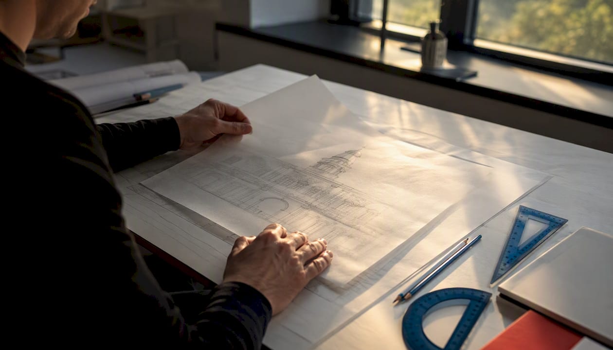
The practical value is speed. Drafting only half of a symmetric object and mirroring it to complete the other half is a standard productivity practice in architecture and technical drafting. It eliminates the small mismatches that creep in when you draw both halves manually.
Common situations where MIRROR saves real time:
Building elevations: Draw the left half of a symmetric facade, mirror it across the centerline.
Mechanical brackets and fixtures: One side is identical to the other — draw once, mirror once.
Furniture and fixture layouts: Repeat a bathroom or kitchen layout in a mirrored configuration.
Detail work: Copy a door or window detail to the opposite side of a plan without redrawing.
MIRROR is available in both full AutoCAD and AutoCAD LT. The 3D variant, MIRROR3D, is available in full AutoCAD only — AutoCAD LT is a 2D-only product, so MIRROR3D doesn’t apply there. For a deeper look at when 2D versus 3D workflows make sense for your projects, the AutoCAD 2D versus 3D drafting guide from S15studio is worth reading.
How to use the MIRROR command: 2D step-by-step
The 2D mirror workflow has four steps. Each one maps directly to a prompt you’ll see in the command line at the bottom of the screen.
Activate the command. Type MI and press Enter, or click Home > Modify > Mirror. You can also type _MIRROR at the command line for the full command name.
Select your objects. Click individual objects, drag a selection window, or use a crossing selection. Press Enter when your selection is complete.
Define the mirror line. Pick two points. The line between them becomes the axis of symmetry. Use Object Snaps (OSNAP), Ortho mode (F8), or Polar Tracking to lock the axis to an exact angle — a horizontal, vertical, or angled line. Manual picks without those modes frequently produce off-axis results that need cleanup.
Answer the erase prompt. AutoCAD asks: Erase source objects? [Yes/No] : Press Enter to keep the originals. Type Y and press Enter to delete them.
Here’s what the command line looks like during a typical session:
Command: MI
MIRROR
Select objects: [click objects]
Select objects: [press Enter]
Specify first point of mirror line: [click point 1]
Specify second point of mirror line: [click point 2]
Erase source objects? [Yes/No] <N>: [press Enter or type Y]
As Dummies puts it: accept the default No to retain the original, or type Y to delete it. That’s the whole decision.
Pro Tip: Draw a temporary construction line or use an existing centerline as your mirror axis reference. Snap to its endpoints using OSNAP to guarantee the mirror line is exactly where you intend it.
Understanding the command prompts and options
Every prompt in the MIRROR sequence has a specific purpose. Knowing what each one expects prevents accidental deletions and misaligned copies.
Select objects: Pick everything you want mirrored. You can use window selection (left-to-right drag), crossing selection (right-to-left drag), or click individual objects. Press Enter to confirm.
Specify first point of mirror line: Click the starting point of your axis. This is usually a midpoint, endpoint, or intersection — use OSNAP to lock onto it precisely.
Specify second point of mirror line: Click the second point. The direction between the two points defines the angle of the mirror axis. A perfectly vertical axis requires both points to share the same X coordinate — Ortho mode handles this automatically.
Erase source objects? [Yes/No] : The angle brackets show the default. Press Enter to accept No (keep originals). Type Y to erase the source geometry. There is no undo inside the command — if you erase by mistake, use Ctrl+Z immediately after.
One note for users working across 2D and 3D: the two points you pick in 2D define a line, but that line also implicitly defines a mirroring plane perpendicular to the current UCS. This becomes relevant when the same geometry feeds into a 3D workflow. The AutoCAD LT Help documentation covers this axis behavior in detail for users who need to understand the geometry precisely.
How mirroring affects text, attributes, and hatch patterns
This is where most beginners get caught off guard. Mirroring doesn’t just flip lines — it also affects text, dimensions, and hatch patterns. Two system variables control that behavior.
AutoCAD’s default settings are designed to keep drawings readable, but knowing when to override them matters.
Variable | Default Value | What It Controls | Recommended Setting |
MIRRTEXT | 0 | Whether TEXT, MTEXT, and ATTDEF objects are reversed when mirrored | Keep at 0 for readable annotations |
MIRRHATCH | 0 | Whether hatch pattern direction is mirrored or retained | Set to 1 if you need the hatch to mirror with the geometry |
Key behaviors to know:
MIRRTEXT = 0 (default): Text stays readable after mirroring. A room label on the left side of a plan reads left-to-right after it’s mirrored to the right side.
MIRRTEXT = 1: Text reverses. Useful in rare cases where you need the text itself to appear flipped, such as certain manufacturing templates.
MIRRHATCH: When set to 0, the hatch pattern direction is preserved. When set to 1, the hatch mirrors with the geometry. For most architectural drawings, the default works fine.
Block attributes (constant): Text and constant attributes inside an inserted block may reverse regardless of the MIRRTEXT setting. This exception catches many users by surprise. If you need attribute text to stay readable after mirroring, detach or manage the attributes before running the command.
To change a system variable, type its name at the command line and press Enter, then type the new value.
How MIRROR3D works for 3D geometry
MIRROR3D is the 3D equivalent of MIRROR. Instead of reflecting objects across a line, it reflects them across a mirroring plane. The core concept is the same — pick what to mirror, define the reflection axis — but in 3D, that axis becomes a full plane in space.
Three ways to define the mirroring plane in MIRROR3D:
Plane of a planar object: Pick an existing flat object (a face, a polyline) and AutoCAD uses its plane.
Standard plane through a point: Choose XY, YZ, or XZ, then pick a point the plane passes through.
Three points: Pick any three points in space to define a custom plane.
MIRROR3D also lets you reuse the last defined mirroring plane, which speeds up repetitive 3D work.
Feature | MIRROR (2D) | MIRROR3D |
Mirror axis | Two points define a line | Three methods define a plane |
Typical use | Elevations, plans, details | 3D solids, surfaces, 3D models |
Available in AutoCAD LT | Yes | No |
Available in full AutoCAD | Yes | Yes |
If you’re deciding whether 3D workflows belong in your practice, the AutoCAD 2D versus 3D drafting guide lays out the tradeoffs clearly.
Grip-based mirroring: the faster alternative
The command-line MIRROR workflow is reliable, but grip-based mirroring is faster for small, on-the-fly edits. Experienced drafters use it constantly because it skips the command-mode switch entirely.
Select the object without running any command. Blue grip squares appear.
Click a grip to activate it. It turns red.
Press Enter to cycle through grip modes: Stretch → Move → Rotate → Scale → Mirror.
Pick the second point to define the mirror axis from the active grip.
Hold Ctrl before picking the second point to copy instead of move. Release Ctrl to mirror in place (replacing the original).
Accuracy matters here just as much as in command-line mode. Keep Ortho or Polar Tracking on to constrain the mirror axis to a clean angle. For complex geometry, place a temporary construction line first and snap to its endpoints during the grip operation.
Pro Tip: Grip mirroring is ideal for iterative work — adjusting a repeated detail, flipping a symbol, or testing a mirrored layout before committing. For large selections or precise architectural workflows, the full MIRROR command gives you more control over selection and axis definition.
Why mirrored results look wrong and how to fix them
Most mirroring problems fall into four categories. Each has a fast fix.
Text appears backwards: Check MIRRTEXT. If it’s set to 1, type MIRRTEXT at the command line and change it to 0. If the text is inside a block, MIRRTEXT won’t help — you need to edit the block definition or detach the attribute before mirroring.
Hatch direction is flipped: Check MIRRHATCH. Set it to 0 to preserve the hatch direction, or 1 to mirror it. Re-run the mirror after changing the variable.
Mirror axis is off-angle: The most common cause is picking mirror points without OSNAP or Ortho active. Use Ctrl+Z to undo, turn on Ortho (F8) or set a Polar angle, then redo the mirror from a snapped point.
Geometry doesn’t align with the rest of the drawing: Usually an OSNAP miss. Zoom in before picking mirror points, and snap to a midpoint, endpoint, or intersection rather than clicking freehand.
For a broader look at common AutoCAD errors and their fixes, the common AutoCAD drafting mistakes guide from S15studio covers the patterns that trip up beginners most often.
Pro Tip: Before answering the Erase source objects? prompt, pause and check your mirror result visually. If something looks wrong, press Escape to cancel the command — the source objects are still intact. Undo (Ctrl+Z) also works immediately after if you confirmed too quickly.

When to explode a block before mirroring: if the block contains constant attributes that must stay readable, explode it first (type X at the command line), mirror the resulting geometry, then rebuild the block. It’s extra work, but it’s faster than correcting reversed attributes after the fact.
Worked example: completing a symmetric elevation
Scenario: You’ve drawn the left half of a building elevation to scale. A vertical centerline sits at the midpoint of the facade. You need to mirror the left half to produce the complete elevation.
Set up OSNAP. Make sure Midpoint and Endpoint snaps are active. Turn on Ortho (F8) to constrain the mirror axis to vertical.
Activate MIRROR. Type MI and press Enter.
Select objects. Window-select everything on the left half of the elevation — walls, windows, door, hatch, and any text labels. Press Enter.
Pick the first mirror point. Snap to the top endpoint of the centerline.
Pick the second mirror point. Snap to the bottom endpoint of the centerline. With Ortho on, the axis locks perfectly vertical.
Answer the erase prompt. Press Enter to keep the left half (default No). The right half appears.
Verify the result. Zoom in and check the following:
Verification checklist:
Window and door openings align symmetrically across the centerline.
Text labels are readable on both sides (MIRRTEXT = 0 confirmed).
Hatch patterns face the correct direction on the mirrored side.
Layer assignments are consistent — mirrored objects inherit the source layer.
Dimensions, if any, are not doubled or overlapping.
If you drew the left half with the intent to erase it after mirroring (for example, if you want only the right half as a separate element), type Y at the erase prompt. Otherwise, keep both halves and use the centerline as a reference layer you can freeze later.
Trainer tips from an Autodesk Certified Trainer
Steve Fagan, Autodesk Certified Trainer and founder of S15studio, applies these practices consistently across architectural and technical drawing projects.
Work in half-model workflows. Draw one side of any symmetric object completely — including all details, hatches, and annotations — before mirroring. Mirroring an incomplete half and then editing both sides doubles your work and introduces inconsistencies.
Keep the source until you’ve verified the mirror. Answer No at the Erase source objects prompt every time, at least until you’ve confirmed the mirrored result is correct. Deleting the source before checking is the fastest way to lose work. Undo recovers it, but the habit of verifying first is cleaner.
Store a template with construction geometry. Keep a drawing template that includes standard centerlines and reference geometry for common symmetric layouts — elevations, floor plans, fixture grids. Snapping to existing geometry is faster and more accurate than drawing a temporary mirror axis each time.
Pro Tip: Autodesk’s Knowledge Network is the canonical reference for exact prompt text, system-variable names, and precise MIRROR and MIRROR3D behavior. When in doubt about a variable’s effect, check there first rather than experimenting on a live drawing.
The AutoCAD for architecture guide from S15studio covers how these habits fit into a broader architectural drafting workflow, including layer management and drawing setup practices that make mirroring more predictable.
The part most tutorials skip
Most AutoCAD MIRROR tutorials stop at the four-step workflow and call it done. That’s enough to run the command — but it’s not enough to use it well.
The real skill is knowing when to mirror and what to prepare before you do. Mirroring a half-model that has loose geometry, unsnapped endpoints, or unmanaged block attributes produces a mirrored half that looks right at first glance and causes problems later. The text reversal issue with block attributes is a good example: MIRRTEXT = 0 doesn’t protect you there, and most beginners don’t find out until the drawing is nearly finished.
Grip-based mirroring is another gap. The command-line workflow gets all the attention in tutorials, but experienced drafters reach for grip mirroring constantly for small edits. It’s faster, it keeps you in the drawing context, and it doesn’t require you to pre-select objects before activating a command. Learning both methods and knowing when to switch between them is what separates a competent AutoCAD user from a slow one.
The MIRROR command itself is simple. The judgment around it — half-model discipline, system variable awareness, axis precision, block management — is what takes practice to build.
S15studio AutoCAD training: practice mirroring with real projects
Knowing the MIRROR command is one thing. Using it fluently on a real architectural drawing is another. S15studio’s AutoCAD course gives you project-based practice with the exact workflows covered in this guide — mirroring, symmetry tasks, elevation construction, and the system variable settings that make drawings production-ready.
The course is built by Steve Fagan, Autodesk Certified Trainer, and includes downloadable templates, PDF notes, and direct trainer support. It covers AutoCAD from beginner to advanced level, with exam practice for the Autodesk Certified User (ACU) certification. You get lifetime access to all materials with a single purchase. If you want structured, guided practice rather than piecing together tutorials, start the AutoCAD course at S15studio and work through real drawing projects from day one.
Sources
Recommended
Comments